Section type rectifier for electronic accelerator

A technology of electron accelerators and rectifiers, which is applied in the direction of electrical components, accelerators, etc., can solve the problems of occupying limited internal space of rectifiers, difficult maintenance, and tip discharge, so as to overcome the problem of tip discharge, good rectification effect, and save internal space Effect

Active Publication Date: 2007-07-25
张祥华
View PDF0 Cites 9 Cited by
  • Summary
  • Abstract
  • Description
  • Claims
  • Application Information

AI Technical Summary

Problems solved by technology

Due to the integral casting structure, once a fault occurs, it is difficult to find the fault point and it is very difficult to repair
In addition, this rectifier contains two layers of shielding sleeves inside, and the two layers of shielding sleeves will occupy the limited internal space of the rectifier, so that the rectifier accommodates fewer components such as diodes and capacitors. Therefore, the rectification effect of this rectifier is not good.
On the other hand, since the rectifier works in a high electric field environment, if a monolithic casting structure is adopted, there will inevitably be convex and concave points on the surface, and the convex and concave points can easily cause tip discharge

Method used


Image

  • Section type rectifier for electronic accelerator

Examples


Embodiment Construction

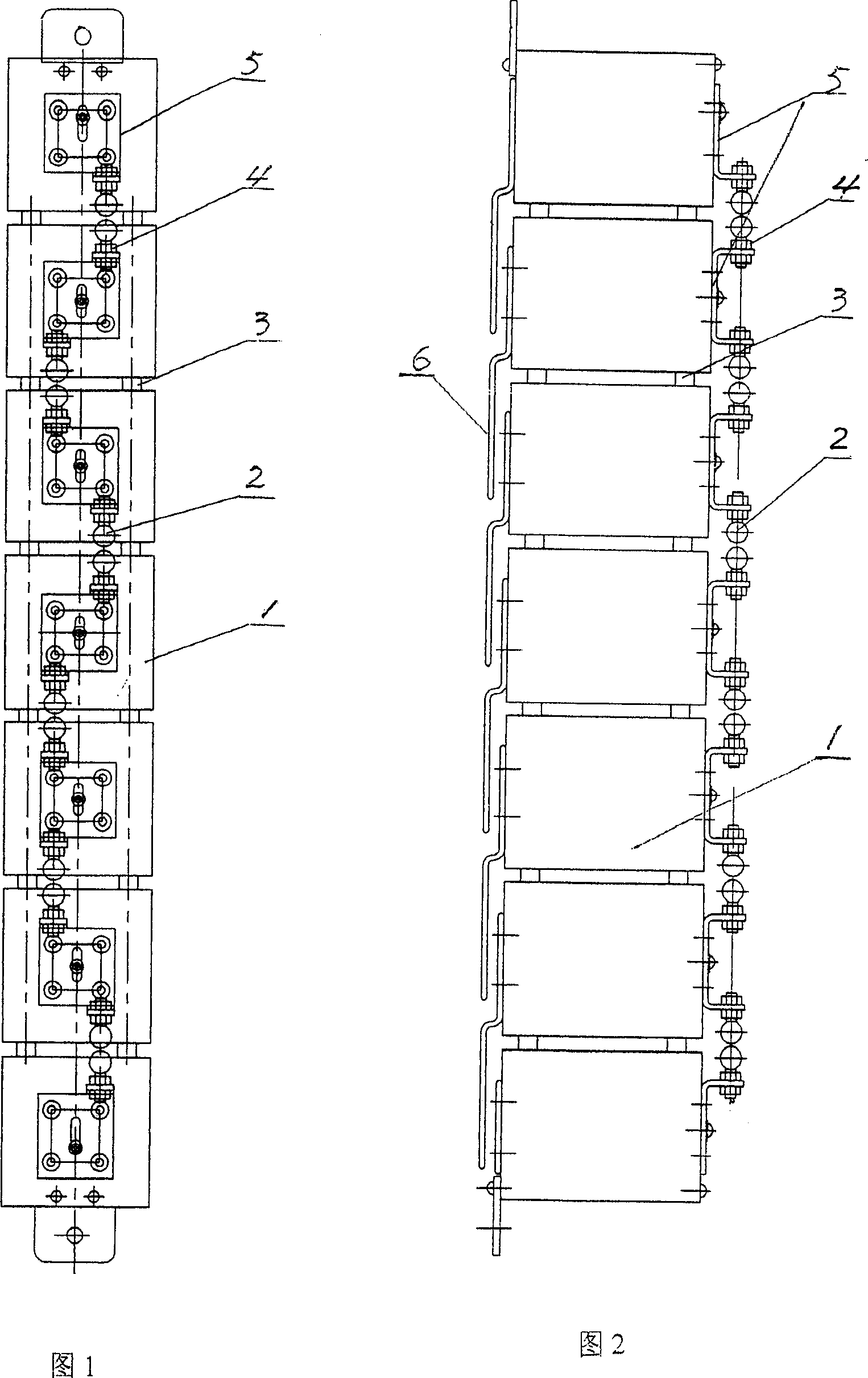
[0011] As shown in Fig. 1 and Fig. 2, the segmented rectifying device for an electron accelerator of the present invention contains seven rectifying boxes 1, and these rectifying boxes 1 are cuboids with shielding sleeves on their outside, and they pass through four connecting rods 3 connected together. The same end surface of the rectifier box 1 is provided with a fixing plate 5, which is processed into a U-shape so that their two ends are tilted upward. The horizontal section of the U-shaped fixing plate 5 is fixed on the end face of the rectifier box 1, and they are arranged along the connection direction of the rectifier box 1, and discharge balls 2 are installed on their two tilted ends. Said discharge ball 2 is all welded with a screw mandrel, and the two ends of the fixed plate 5 are all processed with through holes, and the discharge ball 2 is fixed on the two ends of the fixed plate 5 by means of the nut 4, the screw mandrel on it and the through hole. There is a gap...


PUM


Abstract

The invention comprises multi rectification boxes; each rectification box shapes cuboid, and has a shielding cover on its external surface; the rectification boxes are attached together through link connection, and on all identical end faces of them, the securing plates are respectively installed; on the both end of each securing plate a discharge ball is respectively mounted; a gap is kept between two discharge balls respectively located on the two neighboring plate; the end faces of the rectification boxes opposite to the discharge balls there are shielding plates installed; the shielding plates are secured on the corresponding rectification box, the other end of each rectification box extends out to same direction and is overlapped with other shielding plates on the rectification boxes.

Description

technical field [0001] The invention relates to a rectifying device. Specifically, it is a segmented rectification device on a high-frequency electron accelerator. Background technique [0002] It is known in the electron accelerator manufacturing industry that the high-frequency power of the high-frequency and high-voltage electron accelerator is transmitted to each rectifier through the coupling capacitor, and a DC current flows after rectification. Since each rectifier is connected in series, a large voltage drop will be generated, so that the accelerator obtains a high voltage. Therefore, the rectifier is the core component for generating DC high voltage. [0003] Among them, the high-frequency rectifiers are all traditional rectifiers, and the traditional rectifiers all adopt integral casting structure. Due to the integral casting structure, once a fault occurs, it is difficult to find the fault point and it is very difficult to repair. In addition, this rectifier c...

Claims


Application Information

Patent Timeline
Patent Type & Authority Applications(China)
IPC IPC(8): H05H7/02H05H7/00
Inventor 李兆先张祥华
Owner 张祥华
Why Eureka
Try Eureka