
Method for manufacturing magnetic core component

A manufacturing method and technology of magnetic core, applied in the direction of magnetic core manufacturing, inductor/transformer/magnet manufacturing, transformer/inductor magnetic core, etc., can solve the problems of low magnetic flux density, short circuit of insulating film, high pressure, etc. Effects of packing density, simplification of manufacturing process, and enhancement of magnetic flux density

Active Publication Date: 2007-08-01
NTN CORP
View PDF4 Cites 12 Cited by
  • Summary
  • Abstract
  • Description
  • Claims
  • Application Information

AI Technical Summary

Problems solved by technology

[0011] However, in the case of powder compaction described in Patent Document 1, the pressure applied to the coil is high, and if the insulating coating of the coil is not sufficiently removed, there is a problem that a short circuit occurs.
In addition, when the coil is inserted, the transmission of pressure to the particles constituting the compressed powder compact is likely to become uneven, not only the shape is restricted, but also cracks may occur when the electrode terminal protruding outward is bent. Happening
[0012] In addition, in the manufacturing method of the rotor described in Patent Document 2, although the production efficiency is improved, the characteristics of the magnetic material are not improved, and the magnetic material is not insulated. Therefore, there is a possibility that the AC magnetic properties, especially the DC superposition properties, deteriorate. question
[0013] Furthermore, in the manufacturing method described in Patent Document 3, there is no problem of cracks unlike the insert molding based on compacted powder molding, but since only magnetic resin materials are used, there is low density problem
[0014] In addition, it is also considered to increase the pressure applied to the compressed powder compact or perform press molding at an elevated temperature to increase the packing density of the compact and prevent cracks, but this may lead to an increase in manufacturing costs, or unsuitable for continuous mass production
[0015] In addition, in the case of the compression-molded magnet described in Patent Document 4, since a process of assembling the magnet into the magnetic core is required, there is a problem that it is difficult to improve the production efficiency.
Furthermore, in the state of a compression-molded body, sufficient strength for handling parts cannot be obtained, and there is a possibility of cracks

Method used


Image

  • Method for manufacturing magnetic core component
  • Method for manufacturing magnetic core component
  • Method for manufacturing magnetic core component

Examples


Embodiment approach 1

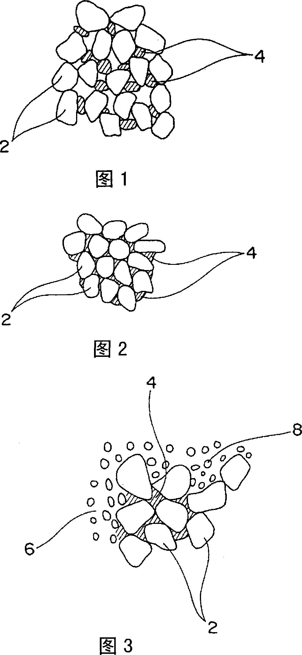
[0057] 1 shows a magnetic body in a powder compacted state used in the manufacturing method of a resin molded magnetic core part according to Embodiment 1 of the present invention, and is contained (dispersed) between a plurality of powder particles 2 constituting magnetic powder covered with an insulating material. ) a plurality of binder particles 4 .

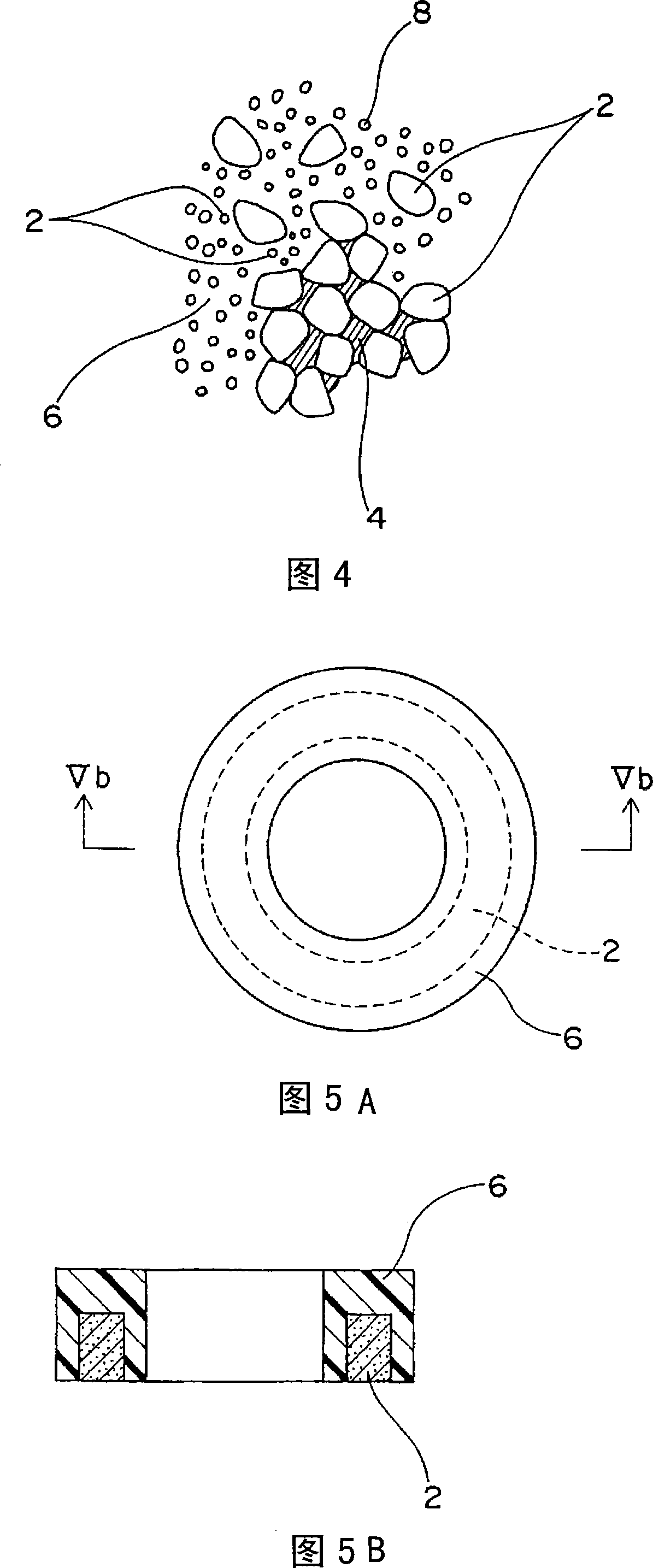
[0058] As the binder 4, a resin having a melting temperature lower than a predetermined injection molding temperature is used, and by injection molding at a predetermined temperature together with a matrix resin containing magnetic powder covered with an insulating material, the binder 4 is melted or Softening, as shown in FIG. 2 , the intervals between the magnetic powder particles 2 become shorter, the compacted magnetic body shrinks, and its filling density increases.

[0059] As the magnetic powder particles 2 , those having excellent soft magnetic properties, for example, those shown below are preferable.

[0060] ·As p...

Embodiment approach 2

[0082] 7A and 7B show a core component manufactured by the method of manufacturing a resin molded core component according to Embodiment 2 of the present invention, showing a case where the core component is a coil-enclosed type magnetic component.

[0083] As shown in FIGS. 7A and 7B , in a state where the lead-out portions 12 at both ends of the coil 10 are drawn in substantially parallel to the same direction, the powder-molded magnetic body 2 is inserted into the coil 10 , and the resin composition 6 is inserted into the coil 10 . By insert molding together, only the lead-out portions 12 at both ends are exposed, thereby partially increasing the magnetic permeability of the resin molded magnetic core member and improving its performance. In particular, when the compressed powder magnetic body 2 is inserted inside the coil 10, the magnetic permeability inside the coil 10 increases, the coil diameter can be set smaller, and the number of revolutions can also be reduced.

[0...

Embodiment approach 3

[0086] 9A and 9B show a magnetic core component manufactured by the method for manufacturing a resin molded magnetic core component according to Embodiment 3 of the present invention, particularly a case where the resin molded magnetic core component is a coil-encapsulated magnetic component.

[0087] In the case of the resin molded magnetic core components shown in FIGS. 9A and 9B , firstly, a wire made of a conductive material such as Cu is wound on a linear rod (not shown) to manufacture the coil 16 , and then the coil 16 is formed from the rod. The prepared coil 16 is extracted from the material, the axis of the coil 16 is bent into a substantially circular shape, and the lead-out parts 18 at both ends are drawn out in the same direction in a substantially parallel manner. Then, the bent coil 16 is insert-molded together with the resin composition 6 so that only the lead-out portions 18 at both ends are exposed, thereby completing the air-core coil-integrated toroid core ex...


PUM


Abstract

Magnetic powder included in a resin composition (6) to be used for injection molding is covered with an insulating material, and a green compact magnetic body (2) or a powder magnet molding (22) is inserted into the resin composition (6).

Description

technical field [0001] The present invention relates to a method for manufacturing a resin-molded magnetic core member of electrical or electronic equipment such as inductors, transformers, antennas (barantennas), choke coils, filters, and sensors. Background technique [0002] In recent years, with the development of miniaturization, high frequency, and high current of electric equipment or electronic equipment, similar countermeasures are required also for magnetic core components. However, the material properties of the current mainstream ferrite materials are close to the limit, and new materials are being explored. Although new materials such as sendust or amorphous (amorphous) foils have been used to replace ferritic materials, they are only used locally. Amorphous powder materials with excellent magnetic properties have also been developed, but their formability is inferior to existing materials, and their practical application is delayed. [0003] In addition, for ...

Claims


Application Information

Patent Timeline
Patent Type & Authority Applications(China)
IPC IPC(8): H01F41/02H01F1/26H01F27/24B29C45/14
CPCH01F41/0206B22F3/225B29C45/14778B29K2995/0008C22C2202/02H01F1/083H01F1/24H01F1/26H01F17/045H01F17/062H01F27/027H01F27/255H01F41/005H01F2017/048H01F41/02B29C45/14
Inventor 松川清乔石原耕三石川和男丰田知宏田中敏和
Owner NTN CORP
Learn More