

Roller type crushing device
A crushing device and roller-type technology, which is applied in grain processing and other directions, can solve problems such as low efficiency, low output, and small contact area, and achieve the effects of reducing noise, increasing output, and increasing contact area
- Summary
- Abstract
- Description
- Claims
- Application Information
AI Technical Summary
Problems solved by technology
Method used
Image

Examples
Embodiment 1
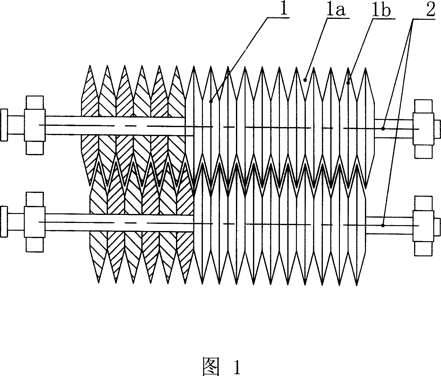
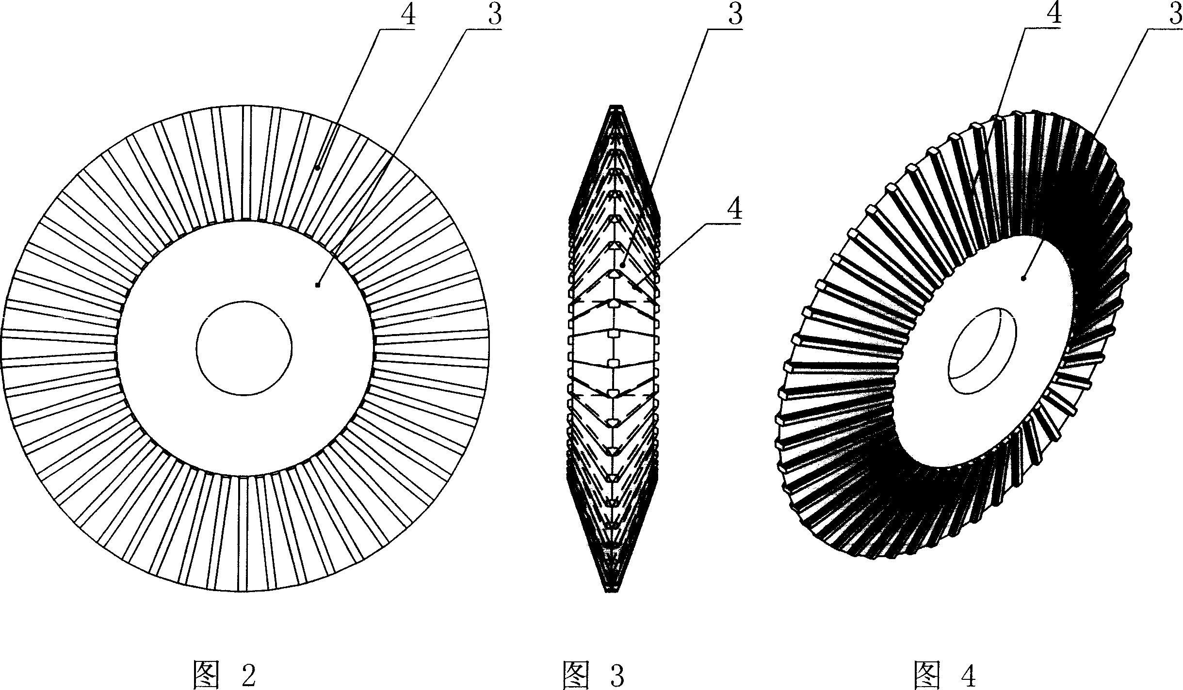
[0024] As shown in Figure 1-4, it is a roller crushing device, which includes a set of main shafts. Zigzag-shaped protrusions 1b and depressions 1a, the protrusions 1b and depressions 1a are distributed in waves along the axial direction of the crushing roller, and the protrusions 1b and depressions 1a on two adjacent crushing rollers coincide with each other and leave a gap; Several convex ridges 4 are provided on the convex and concave surfaces; the above-mentioned crushing roller is composed of several disc knives 3 set on the main shaft 2, and the protrusion 1b and the concave 1a are formed by toothed The outer edges are arranged continuously in the direction of the main axis, and the disc cutter 3 can be scattered parts, as shown in Figure 2-4, so as to facilitate partial replacement; it can also be multiple or even all connected to form a disc cutter assembly , in order to adjust the axial position.
Embodiment 2
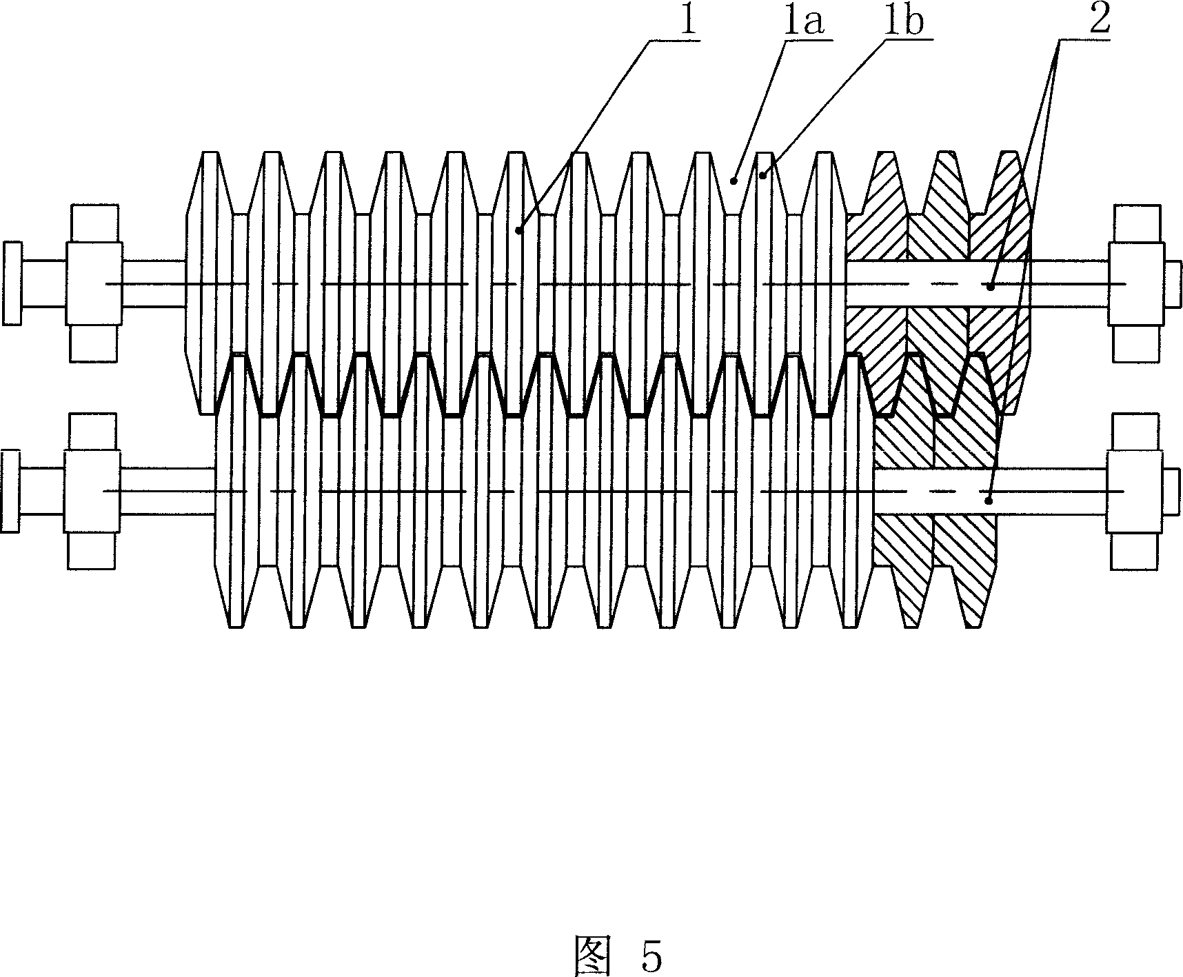
[0026] As shown in Figure 5-9, there is another roller crushing device, which includes two main shafts 2 arranged parallel to each other, and crushing rollers 1 are respectively arranged on the main shafts 2, and several protrusions 1b and depressions 1a are arranged on the crushing rollers 1. The protrusions 1b and depressions 1a are distributed in trapezoidal waves along the axial direction of the crushing rollers, and the protrusions 1b and depressions 1a on two adjacent crushing rollers coincide with each other and leave gaps. As shown in Figure 6-8, the trapezoidal wave can be formed by several disc cutters 3 whose outer edges are positively trapezoidal, and the outer surface of the disc cutter 3 can be provided with raised ridges; as shown in Figure 9, the trapezoidal wave It can also be formed by arranging several disc cutters whose outer edges are inverted trapezoids; the difference is that each disc cutter 3 of an inverted trapezoid must be an independent single piece,...
Embodiment 3
[0028] As shown in Figure 10, it is the third type of roller crushing device, which includes a group of main shafts, which are composed of a plurality of main shafts 2 arranged parallel to each other, and crushing rollers 1 are respectively arranged on the main shafts 2, and several convex rollers are arranged on the crushing rollers 1. Protrusions 1b and depressions 1a, the protrusions 1b and depressions 1a are distributed in waves along the axial direction of the crushing roller, and the protrusions 1b and depressions 1a on two adjacent crushing rollers coincide with each other and leave a gap.
PUM
 Abstract
Description
Claims
Application Information