Processing method and apparatus for rack

A processing equipment and processing method technology, applied in metal processing equipment, mechanical equipment, metal sawing equipment, etc., can solve the problem of relatively high torque output requirements of machine tools, racks that cannot meet processing requirements, and long processing time, etc. problems, to achieve the effect of improving the smoothness, increasing the service life and reducing the amount of grinding

Inactive Publication Date: 2007-08-08
黄开元
View PDF0 Cites 22 Cited by
  • Summary
  • Abstract
  • Description
  • Claims
  • Application Information

AI Technical Summary

Problems solved by technology

[0002] In the prior art, the processing method of the rack uses milling cutters of different standards to directly grind the raw materials. For the rack with small modulus, this processing is relatively simple and convenient; but when the modulus of the rack increases , it is not suitable to use the milling cutter to directly grind into teeth, so people usually plan the rack blank by planing with a planer, but because the entire tooth shape needs to be planed out, the amount of planing will become very large Large, the time required for simultaneous processing will become very long, and when milling the planed rack, the traditional milling cutter is stressed on three sides, which requires a relatively high torque output of the machine tool. It is also quite large. If the tool is worn to a certain extent and continues to be used for the processing of the rack, it is easy to cause the rack to fail to meet the required processing requirements.

Method used


Image

  • Processing method and apparatus for rack
  • Processing method and apparatus for rack
  • Processing method and apparatus for rack

Examples


Embodiment Construction

[0049] Referring to the accompanying drawings, the present invention provides a rack processing method, comprising the following steps:

[0050] a. Place the blank 91 to be processed on the drilling machine, predetermine the specifications of the tooth grooves 95 to be processed, and drill holes 92 on the blank 91 according to the preset tooth grooves 95 (as shown in Figures 19-21), to ensure The hole 92 is tangent to the groove bottom 96 of the formed alveolar 95, and the surfaces where the hole 92 and the groove walls 97 on both sides of the alveolar 95 are located are also tangent to each other;

[0051]B, cut along the groove wall 97 of the tooth groove 95 with a saw, remove the scrap piece 93 after cutting, and obtain the preliminary formed tooth rack 94' (seeing in Figure 22);

[0052] c. Carry out milling processing to the preliminary formed rack 94' to obtain the required rack 94 (see Figure 23).

[0053] Wherein, the milling processing method of step c is to feed the...


PUM

PropertyMeasurementUnit
angleaaaaaaaaaa

Abstract

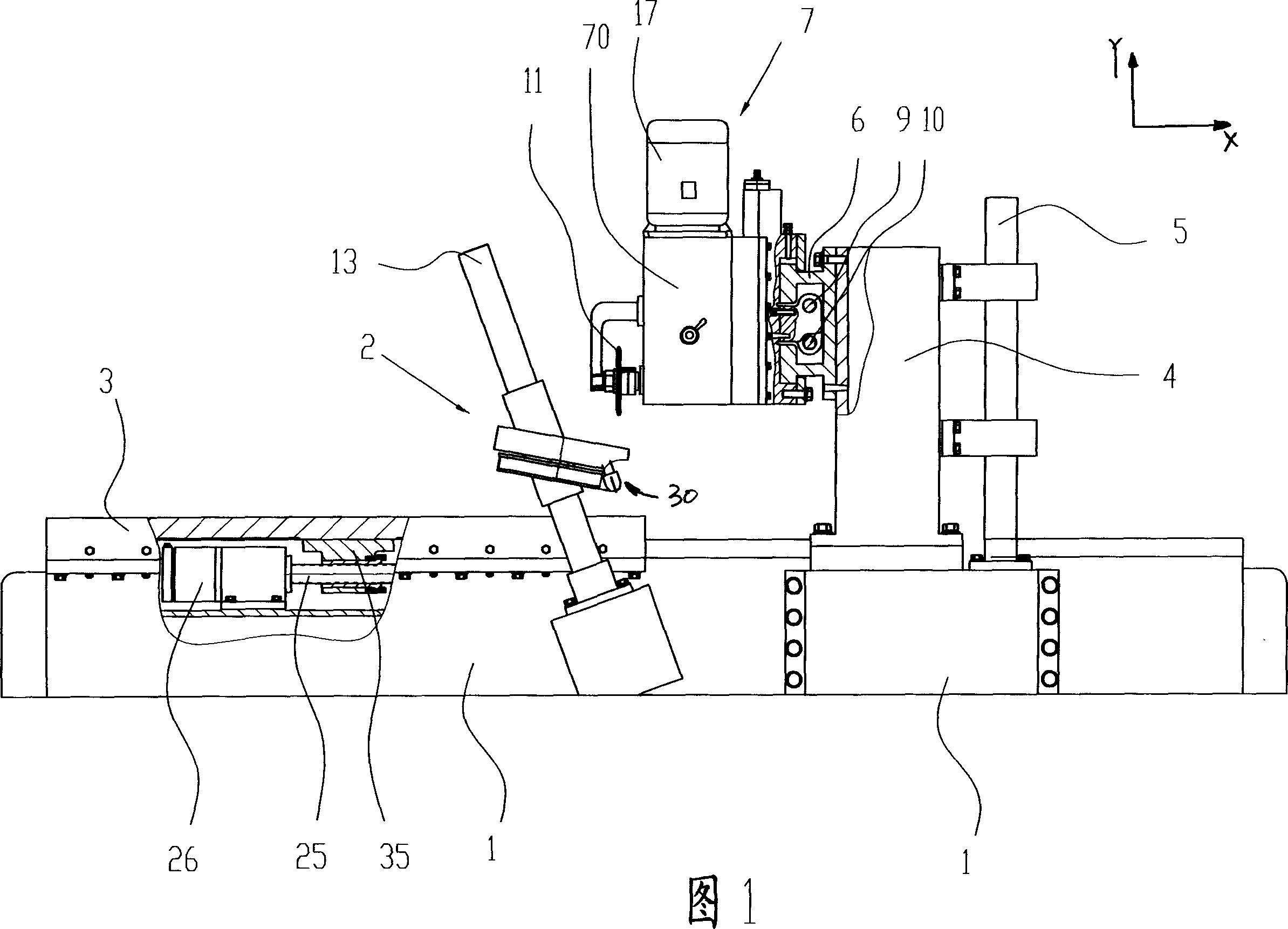
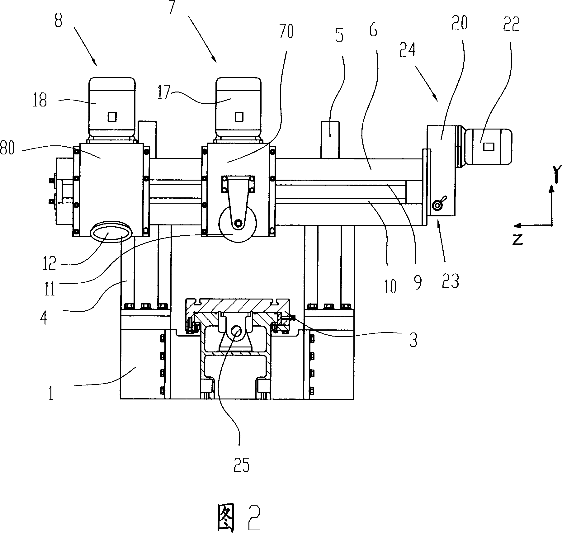
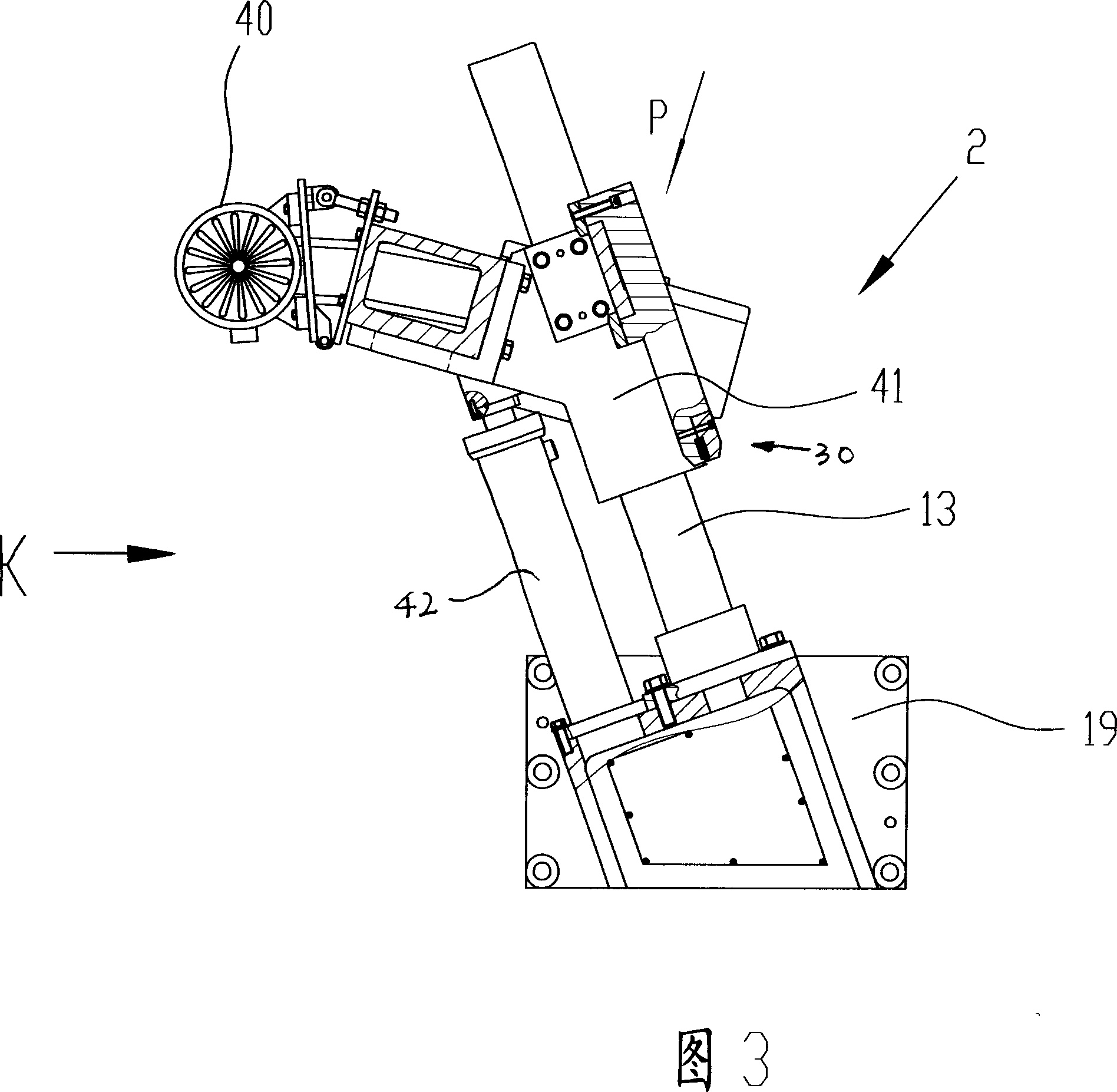
A rack machining comprises drilling on the blank, cutting slot along the tangential line of the hole, milling the gear slot to form the rack, with less grinding effort and machining time with improved machining efficiency. The rack machining equipment comprises a machine base, working bench along the X axis in action, vertical post along Y axis, beam fixed with the post, No.2 milling device on the said beam along the Z axis in motion, with the second milling device composed No.2 generator, rotor shaft of the No.2 generator connected with No.2 gear box in motion, No.2 milling tool wit same output shaft and connected with the No.2 gear box, with the axle line of the output shaft of the No.2 gear box having a inclination angle of 20 degree with the said working bench.

Description

technical field [0001] The invention relates to a processing method of a rack and a device for implementing the processing method. Background technique [0002] In the prior art, the processing method of the rack uses milling cutters of different standards to directly grind the raw materials. For the rack with small modulus, this processing is relatively simple and convenient; but when the modulus of the rack increases , it is not suitable to use the milling cutter to directly grind into teeth, so people usually plan the rack blank by planing with a planer, but because the entire tooth shape needs to be planed out, the amount of planing will become very large Large, the time required for simultaneous processing will become very long, and when milling the planed rack, the traditional milling cutter is stressed on three sides, which requires a relatively high torque output of the machine tool. It is also quite large, and if the tool that wears to a certain extent continues to...

Claims


Application Information

Patent Timeline
Patent Type & Authority Applications(China)
IPC IPC(8): B23P15/14B23F5/20B23Q5/34B23P23/02B23D55/06B23D55/10B23Q5/36
Inventor 黄开元
Owner 黄开元
Why Eureka
Try Eureka