Corrosion resistant marsh gas tank and manufacturing method thereof

A manufacturing method and biogas tank technology, applied to biochemical equipment and methods, gas production bioreactors, biochemical instruments, etc., can solve problems such as easy generation of pores or delamination, uneven coating of slurry, and increase of unfavorable links , to achieve the effect of improving construction production efficiency, uniform slurry distribution and long service life

A manufacturing method and biogas tank technology, applied to biochemical equipment and methods, gas production bioreactors, biochemical instruments, etc., can solve problems such as easy generation of pores or delamination, uneven coating of slurry, and increase of unfavorable links , to achieve the effect of improving construction production efficiency, uniform slurry distribution and long service life

CN101012435BInactive Publication Date: 2010-12-08陈斌

Image

  • Corrosion resistant marsh gas tank and manufacturing method thereof
  • Corrosion resistant marsh gas tank and manufacturing method thereof

Examples


Embodiment 1

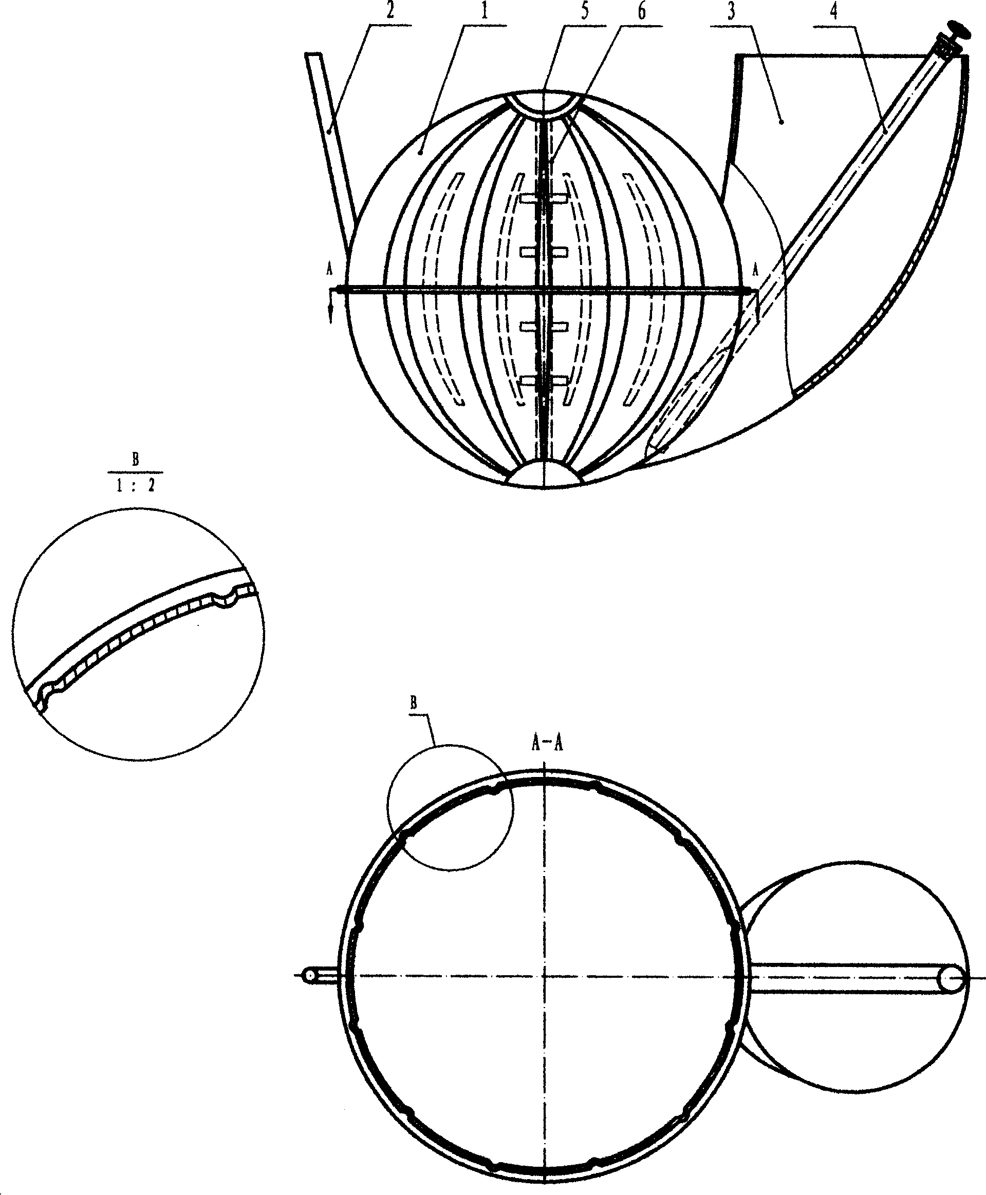
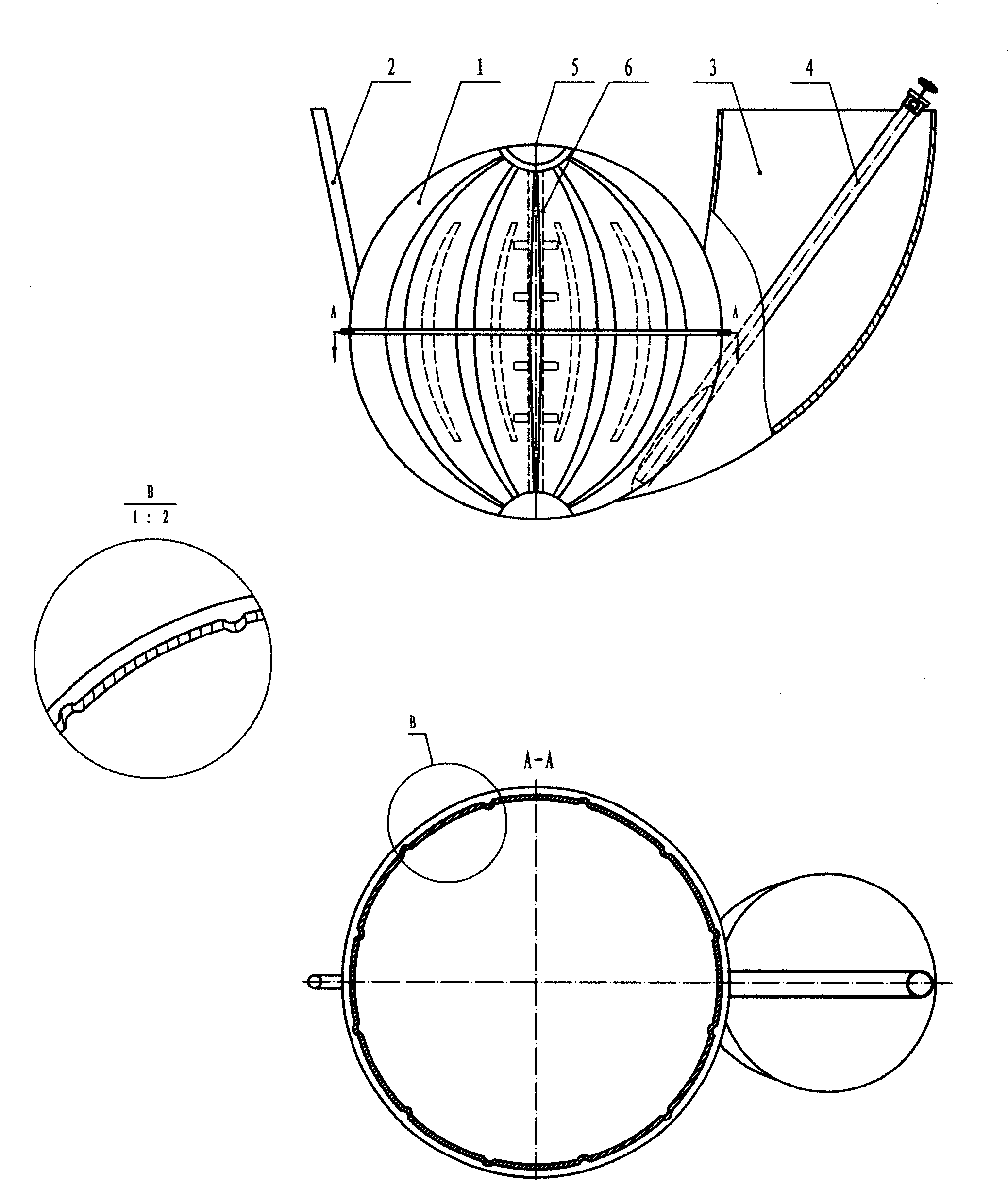
[0012] A novel corrosion-resistant biogas tank includes a tank body (1), a feed inlet (2), a water pressure chamber (3) and a slag extractor (4). The tank body is spherical, the feed liquid enters the tank body from the feed port, and there is a vent hole on the top of the tank body. After the biogas slurry is fermented in the tank body, gas is generated, which is comprehensively utilized through the gas outlet through the pipeline; it is made separately The special slag extractor is inserted into the hydraulic room to extract slag.

Embodiment 2

[0014] The surface of the novel rot-resistant biogas tank (1) is composed of an inwardly or outwardly concave-convex multi-arch hyperbolic structure, and the material of the tank (1) is sprayed with compressed air through a slurry spray gun for slurry spray coating. The middle part of the tank body (1) is provided with a shell-breaking post made of a vertically erected anti-corrosion material, on which several anti-corrosion-treated shell-breaking rods are fixed.


PUM


Abstract

The invention discloses a developed methane tank structure and making method, which comprises the following parts: multiple vaulted hyperbolic structure on the surface, slag collecting hole, hydraulic chamber and integrated manhole and three holes.

Description

technical field [0001] The invention is an advanced biogas tank structure and manufacturing method, and is also applicable to various geometrically shaped tanks, shells and other containers made of organic or inorganic glass fiber reinforced plastics. technical background [0002] The new corrosion-resistant biogas tank is an environmentally friendly and energy-saving gas equipment, especially suitable for rural areas and small towns in my country, and should be vigorously promoted. However, the existing biogas tanks are very troublesome in manufacture, installation and transportation, which hinders the popularization and use of biogas to a certain extent. There are three main manufacturing methods: ①The tank body made of traditional composite materials is mostly made of thin-walled or thick-walled arc plate structure, and some biogas tanks are decomposed into small pieces of arc plate, arc-shaped There are concave and convex flanges at the joints of the boards, and then bo...

Claims


Application Information

Patent Timeline
08 Dec 2010
Publication
CN101012435B
IPC
C12M1/107
CPC
C12M27/02; Y02E50/343; C12M21/04; C12M39/00; C12M23/46; C12M23/02; Y02E50/30
Inventors
陈斌