
Torque convertor

A technology of torque converter and coupling, applied in the field of torque converter, can solve the problems of complex structure, low power and low efficiency of torque converter, and achieve the effect of simple structure, high average speed and easy maintenance

Pending Publication Date: 2007-08-08
吴志强
View PDF0 Cites 64 Cited by
  • Summary
  • Abstract
  • Description
  • Claims
  • Application Information

AI Technical Summary

Problems solved by technology

[0002] At present, torque converters are designed according to principles such as hydrostatics, and the power they can transmit is not high, and the efficiency is not high; in addition, these torque converters are complex in structure, so the cost is high

Method used


Image

  • Torque convertor

Examples


Embodiment

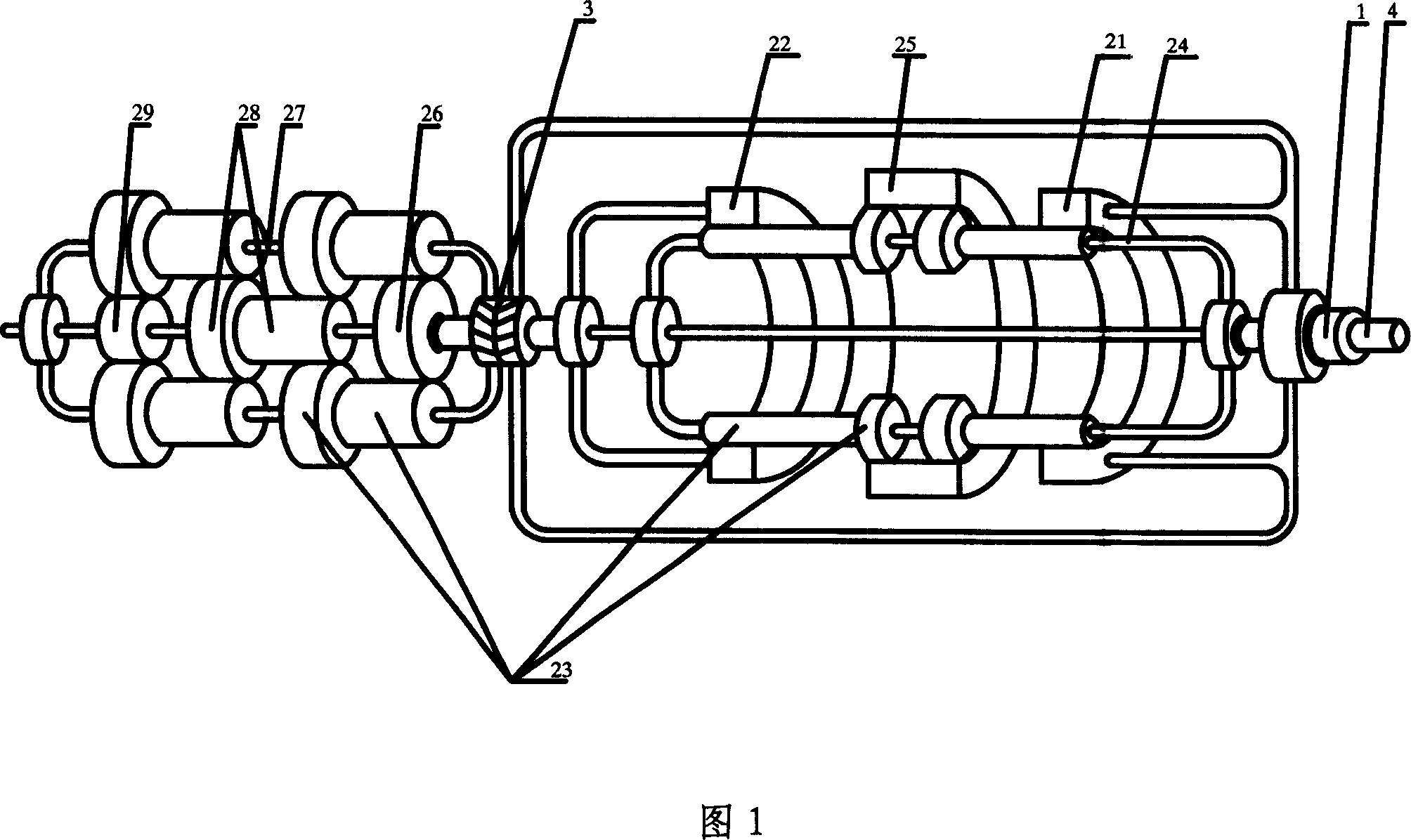
[0018] As shown in Figure 1, a torque converter includes an input shaft 1, a coupling 3, and an output shaft 4, and an input ring gear 21, an output ring gear 22, and a planetary gear are arranged between the input shaft 1 and the output shaft 4. 23. Common output planetary carrier 24, coupling ring gear 25, bull gear 26, common planetary carrier 27, coupling gear 28, pinion gear 29, input ring gear 21 is connected with input shaft 1, and the planets on the common output planetary carrier 24 The gear 23 is connected with the common output planet carrier 24 and the connecting ring gear 25, and the connecting ring gear 25 is connected with the output ring gear 22 and the common output planet carrier 24 through another group of planetary gears 23 on the common output planet carrier 24, and the output ring gear 22 is connected with the bull gear 26, and the bull gear 26 is connected with the common planetary carrier 27 and the connecting gear 28 through the planetary gear 23 on the...


PUM


Abstract

The invention provides a torque changer for prolong the service lives of engine and transmitter. The invention comprises an input axle 1, a connector 3, and an output axle 4. The input axle 1 and the output axle 4 are arranged with an input tooth ring 21, an output tooth ring 22, a planet gear 23, a public output planet support 24, a connecting tooth ring 25, a large gear 26, a public planet support 27, a connecting gear 28, and a small gear 29 between them. The input tooth ring 21 is connected to the input axle 1, and connected to the public output planet support 24 and the connecting tooth ring 25 via the planet gear 23. The connecting tooth ring 25 is connected to the output tooth ring 22 and the public output planet support 24 via the planet gear 23. The output tooth ring 22 is connected to the large gear 26. The large gea3 26 is connected to the public planet support 27 and the connecting gear 28 via the planet gear 23. The connecting gear 28 via the planet gear 23 is connected to the public planet support 27 and the small gear 29. The small gear 29 is connected to the external elements. The public planet support 27 is connected to the input tooth ring 21 via the connector 3. The public output planet support 24 is connected to the output axle 4.

Description

technical field [0001] The invention belongs to the field of speed change, more specifically, it is a gear for various ground vehicles, ships, railway locomotives, engineering machinery, various aerospace, aircraft, metallurgy, mining, petroleum, chemical industry, light industry, food, textile , Lifting and transportation machinery, machine tools, robots and military torque converters. Background technique [0002] At present, torque converters are designed according to principles such as hydrostatics, and the power they can transmit is not large, and the efficiency is not high; in addition, these torque converters are complex in structure, so the cost is high. Contents of the invention [0003] The invention overcomes the deficiencies of the prior art and provides a low-cost, energy-saving and high-efficiency torque converter that prolongs the service life of the engine and the transmission system. [0004] In order to realize the purpose of the present invention, the t...

Claims


Application Information

Patent Timeline
Patent Type & Authority Applications(China)
IPC IPC(8): F16H3/44F16H47/00
Inventor 吴志强
Owner 吴志强
Learn More