
Online alignment device of Y-type waveguide chip and polarization maintaining fiber and online alignment method thereof

A polarization-maintaining optical fiber and waveguide chip technology, applied in the coupling of optical waveguides, can solve problems such as poor consistency, low alignment accuracy, and low efficiency, reduce production costs and defective rate, and solve poor alignment accuracy High, overcome the effect of the connection method

Inactive Publication Date: 2007-08-15
BEIHANG UNIV
View PDF0 Cites 15 Cited by
  • Summary
  • Abstract
  • Description
  • Claims
  • Application Information

AI Technical Summary

Problems solved by technology

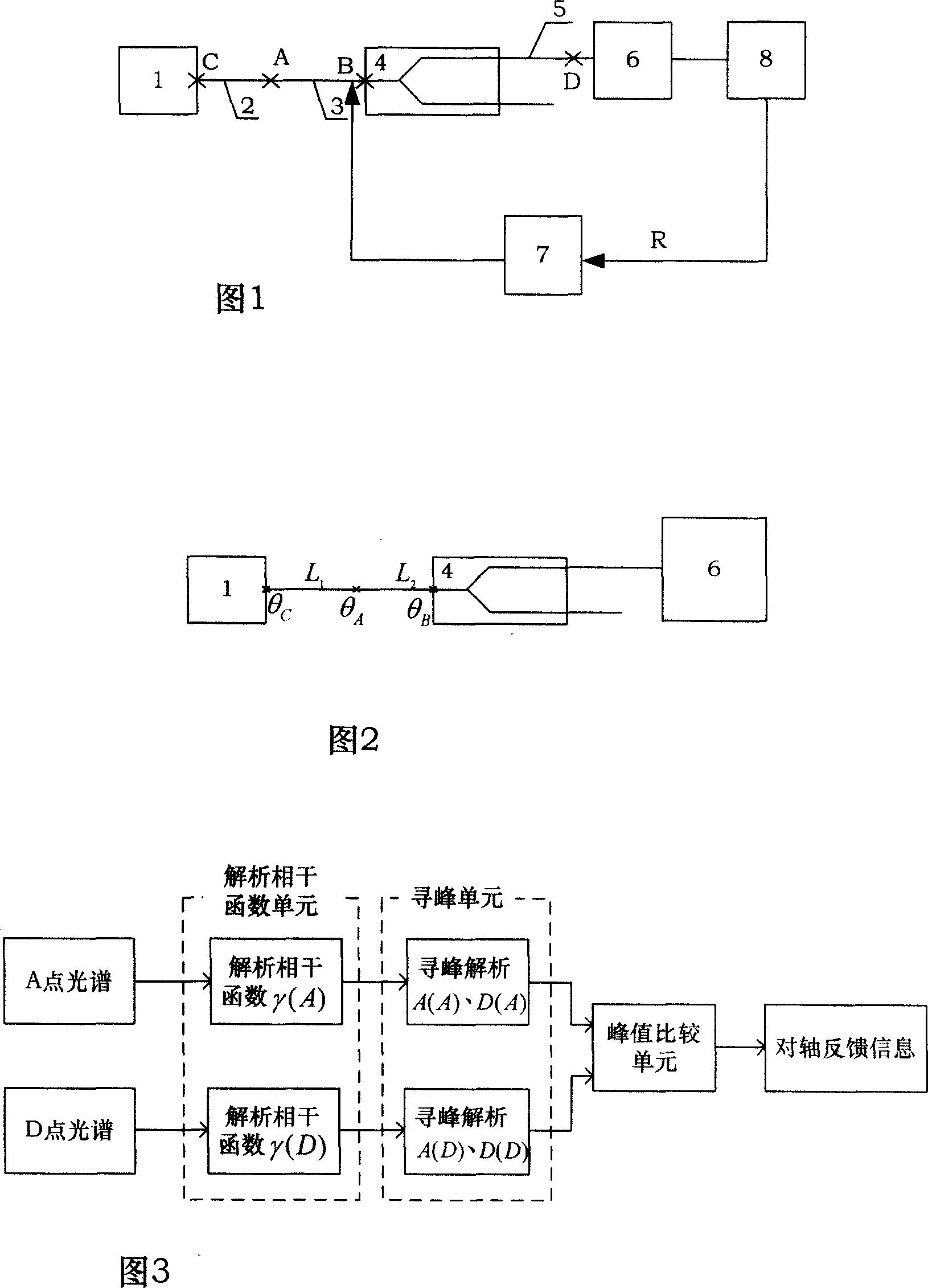
The polarization-maintaining fiber 3 must be completely aligned with the input pigtail of the Y-waveguide chip 4, that is, the fast and slow axes of the polarization-maintaining fiber 3 and the Y-waveguide chip 4 are completely aligned (the fast axis is defined as the x axis, and the slow axis is defined as y), in order to give full play to the high polarization suppression capability of the Y-waveguide chip 4, and if the polarization-maintaining fiber 3 and the Y-waveguide chip 4 cannot align well, a larger polarization cross-coupling will be brought in the fiber optic gyroscope input channel , which affects the output optical power of the Y waveguide chip 4 and the modulation degree of its spectrum, thus bringing a certain impact on the fiber optic gyroscope
[0003] At present, the Y-waveguide input pigtail alignment method used in domestic fiber optic gyroscopes is to artificially adjust the angle by using the relative position of the two stress regions of the input polarization-maintaining pigtail and the cross-section of the Y-waveguide chip under a microscope, which cannot achieve online real-time alignment. Axis, and due to the unsatisfactory shape of the stress area of ​​the polarization maintaining fiber and the Y waveguide chip, the alignment accuracy is not high, the efficiency is low, and the consistency is poor

Method used


Image

  • Online alignment device of Y-type waveguide chip and polarization maintaining fiber and online alignment method thereof
  • Online alignment device of Y-type waveguide chip and polarization maintaining fiber and online alignment method thereof
  • Online alignment device of Y-type waveguide chip and polarization maintaining fiber and online alignment method thereof

Examples


Embodiment

[0075] Without loss of generality, set the fiber length L of the light source pigtail 2 1 =1.5m, the fiber length L of the polarization maintaining fiber 3 2 =1m, the coupling angle θ of the coupling point C C =10°, the welding angle θ of melting point A A = 43°.

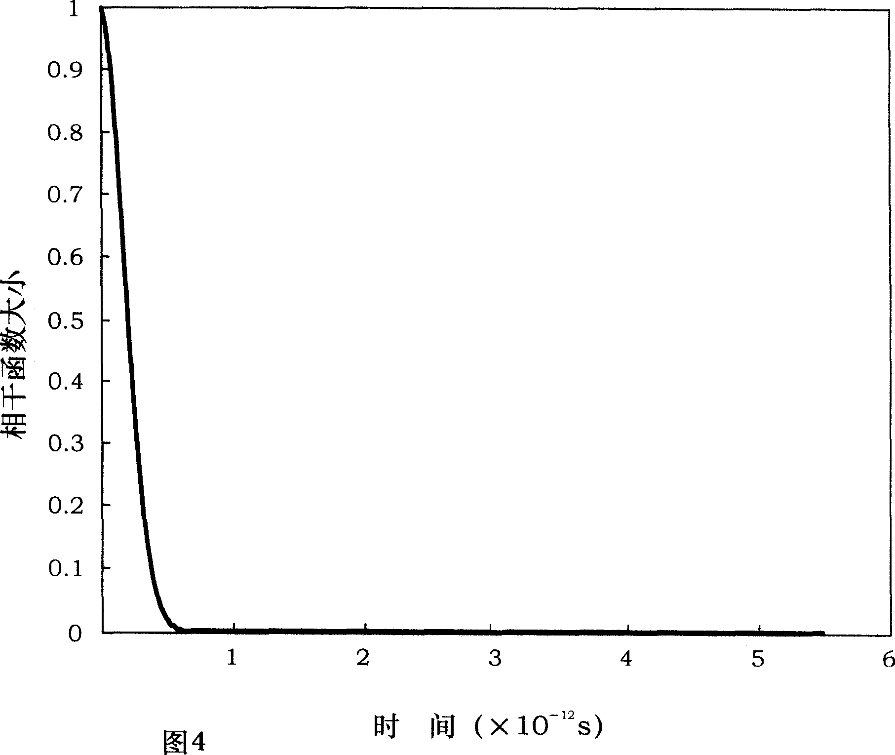
[0076] (A) Measure the spectrum of the light emitted from the light source 1 after passing through the light source pigtail 2 to the melting point A, and analyze the corresponding light source coherence function γ(A) by using the "axis feedback module", as shown in Figure 4 , In the figure, except for the main peak, there are no other secondary peaks.

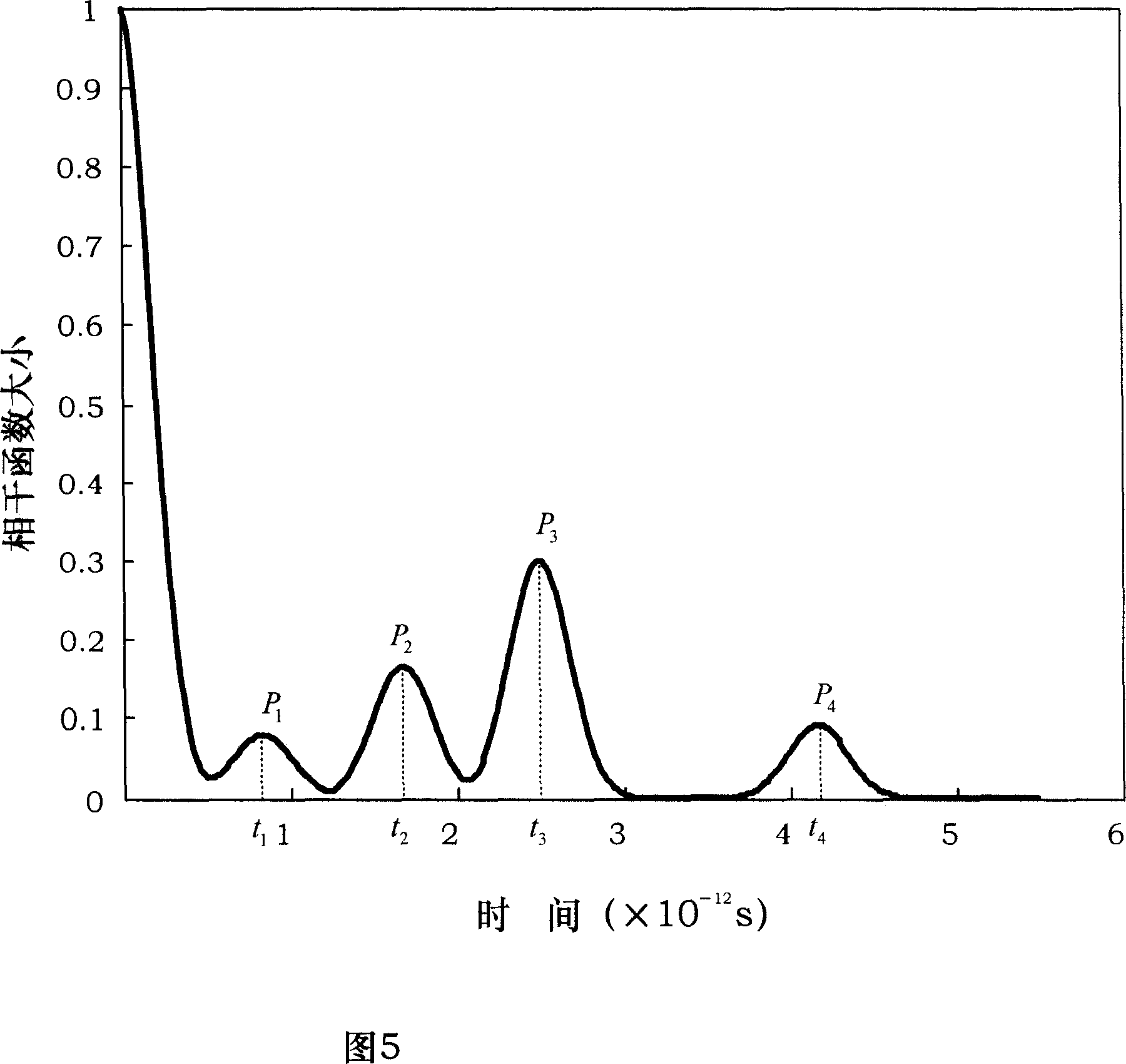
[0077] (B) Fusion splice the light source pigtail 2 and Y waveguide input pigtail 3, the splicing angle is θ A , Suppose the initial alignment angle θ of the polarization-maintaining fiber 3 and the Y-waveguide chip 4 R =15°, the spectrum is tested by the spectrometer 6, and the coherence function γ(D) of the Y waveguide is analyzed by the computer 8 and the axis feedbac...


PUM


Abstract

This invention discloses one Y waveguide chip and ensures bias fiber online alignment method, wherein, the device is set with light source, bias fiber, Y waveguide chip, light spectrum device, computer, pair axis feedback module and executive structure to rotate fiber. The invention method comprises the following steps: using light source emission light through Y wave guide chip to connect D point spectrum by the device and to analyze relative function information by use of feedback module; then using said relative function information to analyze Y wave guide chip and the bias fiber and feedback information R to executive structure.

Description

Technical field [0001] The invention relates to a device for aligning a Y waveguide chip and a polarization-maintaining optical fiber on-line and a method thereof. Background technique [0002] The Y waveguide is an important component in the interferometric closed-loop fiber optic gyroscope. It is based on LiNbO 3 The proton exchange method is used on the substrate to obtain an effect similar to that of a single-polarization guided wave, allowing only the TE mode to pass, while preventing the TM mode from passing, so it has a high polarization suppression capability. The polarization-maintaining fiber 3 as the input pigtail of the Y-waveguide chip 4 must be completely aligned with it, that is, the fast and slow axes of the polarization-maintaining fiber 3 are perfectly aligned with the fast and slow axes of the Y-waveguide chip 4 (the fast axis is defined as the x axis and the slow axis is defined as y) In this way, the high polarization suppression capability of the Y-waveguide...

Claims


Application Information

Patent Timeline
Patent Type & Authority Applications(China)
IPC IPC(8): G02B6/27G02B6/24
Inventor 伊小素徐小斌宋凝芳金靖潘雄李敏
Owner BEIHANG UNIV
Learn More