Contact surface positive pressure varying piezoelectric rotating driver

A rotary drive, positive pressure technology, applied in piezoelectric/electrostrictive or magnetostrictive motors, generators/motors, electrical components, etc., can solve the complex control circuit of asymmetric wave signals, change friction Force and other problems, to achieve the effect of large stroke drive, small movement influence, and simple drive circuit

Inactive Publication Date: 2007-08-15
JILIN UNIV
View PDF0 Cites 5 Cited by
  • Summary
  • Abstract
  • Description
  • Claims
  • Application Information

AI Technical Summary

Problems solved by technology

[0003] The present invention proposes a positive pressure change type piezoelectric rotary driver on the contact surface to solve the problem that the control circuit for generating asymmetric wave electric signals is relatively complicated, and to change the friction force mechanically

Method used


Image

  • Contact surface positive pressure varying piezoelectric rotating driver
  • Contact surface positive pressure varying piezoelectric rotating driver

Examples


Embodiment 1

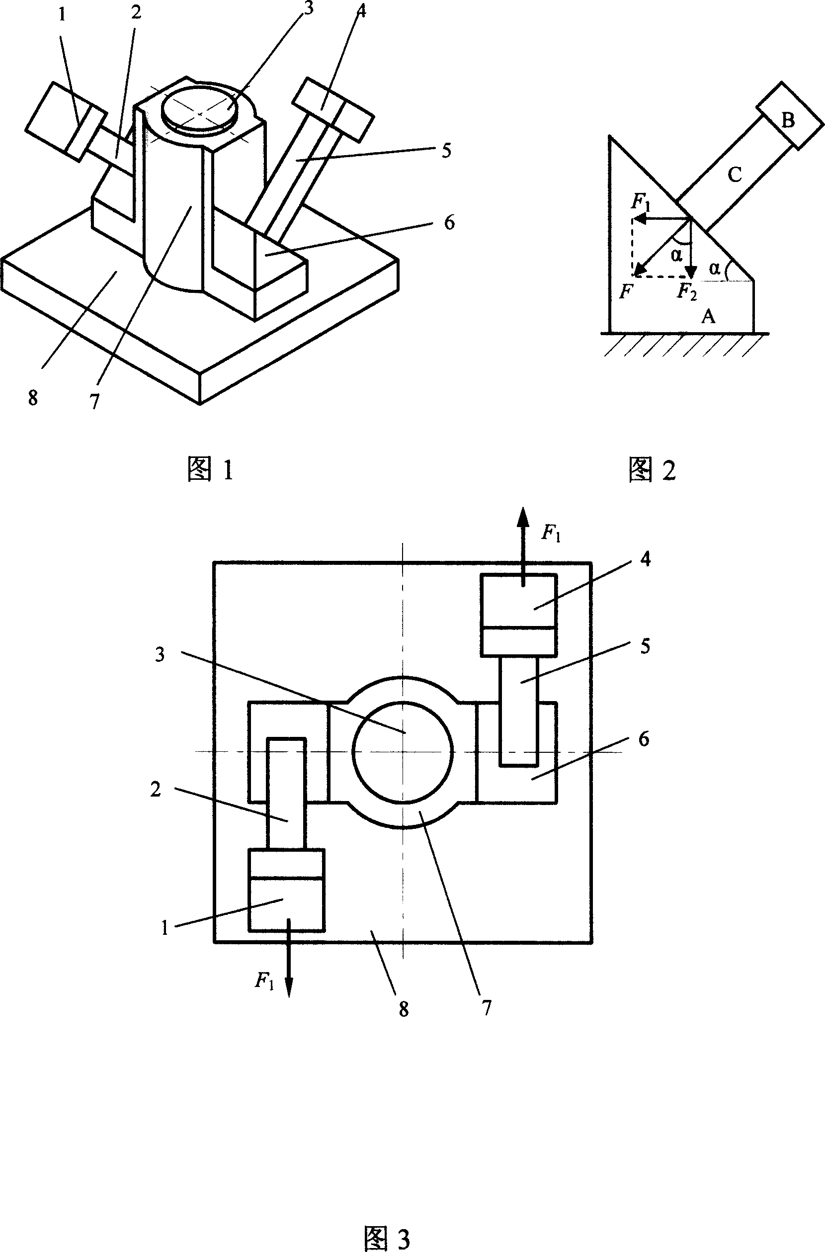
[0014] The shaft 3 is fixedly connected to the driver base 8, the shaft sleeve 7 is connected to the base 8 in rotation, the shaft sleeve 7 rotates around the geometric center of the shaft 3, and the ends of the piezoelectric stack 1 2 and the piezoelectric stack 2 5 are respectively bonded to the adjustment triangular block 6 On the inclined surface, the other end is respectively bonded with the inertial mass block 1 and the inertial mass block 2 4, the piezoelectric stack 1 2 and the inertial mass block 1 constitute the piezoelectric stack vibrator 1, and the piezoelectric stack 2 5 is connected to the inertial mass block 1. The mass block 2 4 constitutes the piezoelectric stack vibrator 2, and the adjustment triangular block 6 is fixedly connected with the driving platform on the shaft sleeve 7. The piezoelectric stack vibrator 1 and the piezoelectric stack vibrator 2 are arranged symmetrically at 180°, and installed in reverse. And it is the same as the included angle α of ...

Embodiment 2

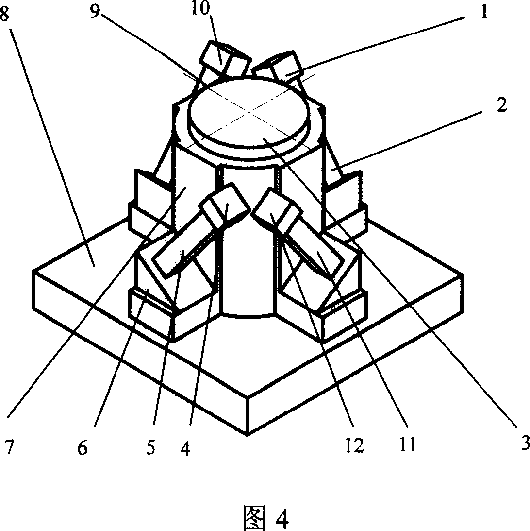
[0020] As shown in Figure 4. The shaft 3 is fixedly connected to the driver base 8, the shaft sleeve 7 is rotationally connected to the base 8, the shaft sleeve 7 rotates around the geometric center of the shaft 3, and the ends of the piezoelectric stack 1 2 and the piezoelectric stack 2 5 are respectively bonded to the adjustment triangular block 6 On the inclined surface, the other end is respectively bonded with the inertial mass block 1 and the inertial mass block 2 4, the piezoelectric stack 1 2 and the inertial mass block 1 constitute the piezoelectric stack vibrator 1, and the piezoelectric stack 2 5 is connected to the inertial mass block 1. The mass block 2 4 constitutes the piezoelectric stack vibrator 2, and the adjustment triangular block 6 is fixedly connected with the driving platform on the shaft sleeve 7. The piezoelectric stack vibrator 1 and the piezoelectric stack vibrator 2 are arranged symmetrically at 180°, and installed in reverse. And it is the same as ...


PUM


Abstract

The related piezoelectric rotatable driver with variable normal pressure on touch surface comprises: a shaft fixed on a base, a shaft lining rotatable connected the base, two one end of piezoelectric stacks bound on oblique surface of a triangular block, another end bound with inertial mass blocks (1, 2). Wherein, the stack 2 / 1 and inertial mass block 2 / 1 form piezoelectric stack oscillator 1 / 2. This invention uses single-path signal, can realize large-range drive, and has little effect on driver motion.

Description

technical field [0001] The invention relates to a piezoelectric precision rotary driver, which uses a piezoelectric stack as a driving source. Background technique [0002] In recent years, with the development of science and technology, research in the fields of optics, electronics, aviation, aerospace, machinery manufacturing, robotics, seismology, biology, medicine, and genetic engineering is in urgent need of submicron and nanoscale micro-displacement technology to achieve micro- / nano-level micro-operations. As the core component of the micro-operating system, the development of precision drives has become an important symbol of the development level of the micro-operating system. The current piezoelectric inertial drive mechanism mainly utilizes the inverse piezoelectric effect of the piezoelectric element, adopts asymmetric waveform excitation to form a two-way asymmetric inertial impact force, cooperates with the fixed friction force and organically combines the appr...

Claims


Application Information

Patent Timeline
Patent Type & Authority Applications(China)
IPC IPC(8): H02N2/00H02N2/12
Inventor 曾平赵宏伟程光明华顺明张宏壮杨志刚王宝鹏
Owner JILIN UNIV
Why Eureka
Try Eureka