Athermal AWG and AWG with low power consumption using groove of changeable width

A technology of width and thermal expansion coefficient, applied in the coupling of optical waveguide, instrument, optical waveguide light guide, etc., can solve problems such as crosstalk interference and signal loss

Active Publication Date: 2007-08-15
NEOPHOTONICS CORP
View PDF1 Cites 17 Cited by
  • Summary
  • Abstract
  • Description
  • Claims
  • Application Information

AI Technical Summary

Problems solved by technology

This wavelength shift can cause signal loss and/

Method used


Image

  • Athermal AWG and AWG with low power consumption using groove of changeable width
  • Athermal AWG and AWG with low power consumption using groove of changeable width
  • Athermal AWG and AWG with low power consumption using groove of changeable width

Examples


Embodiment Construction

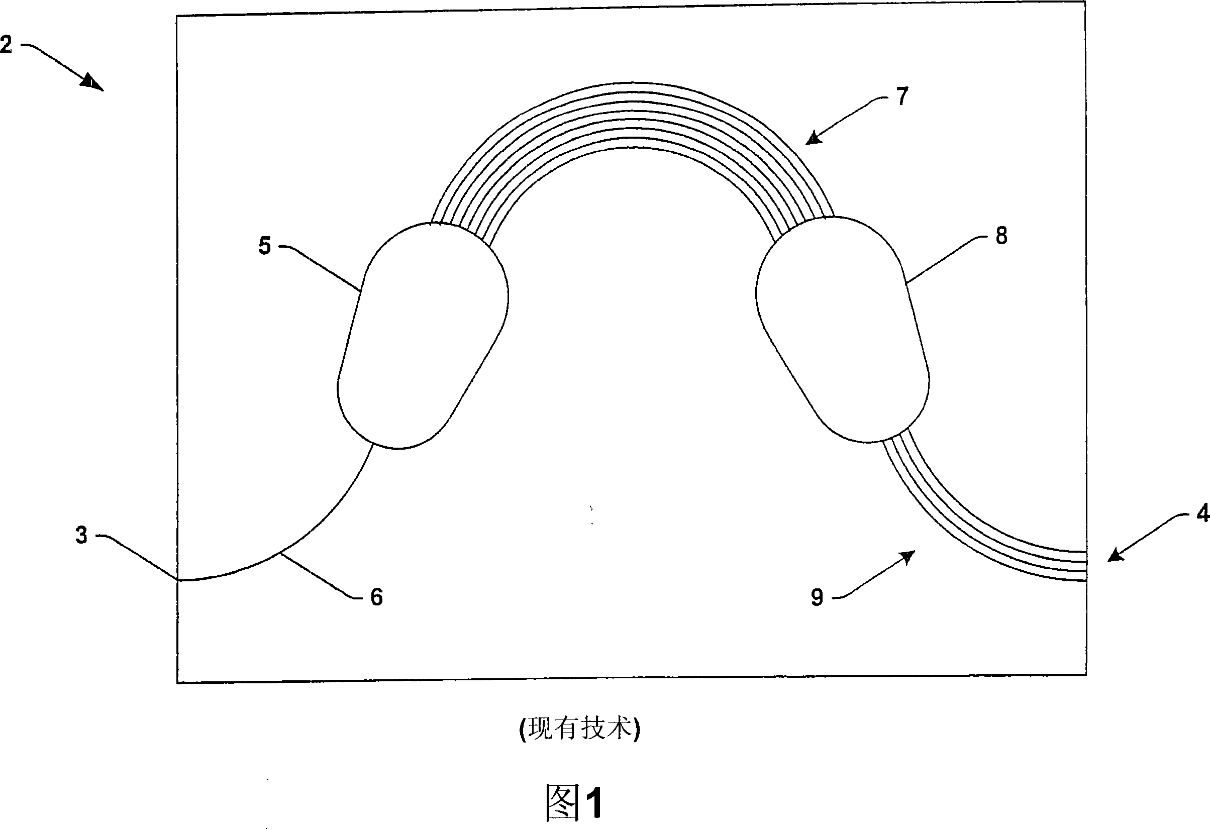
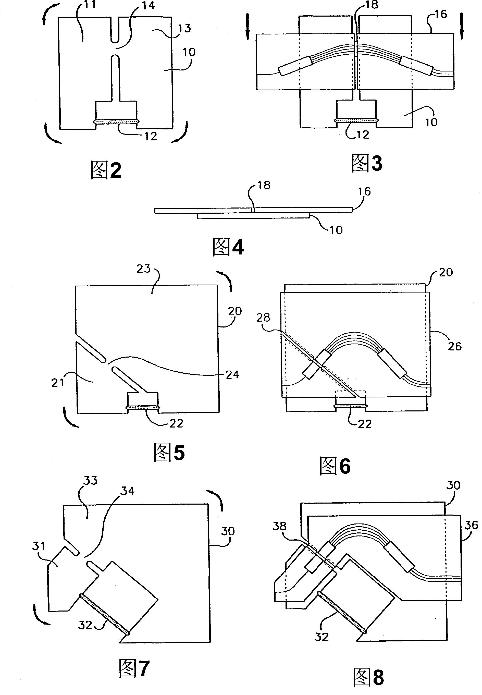
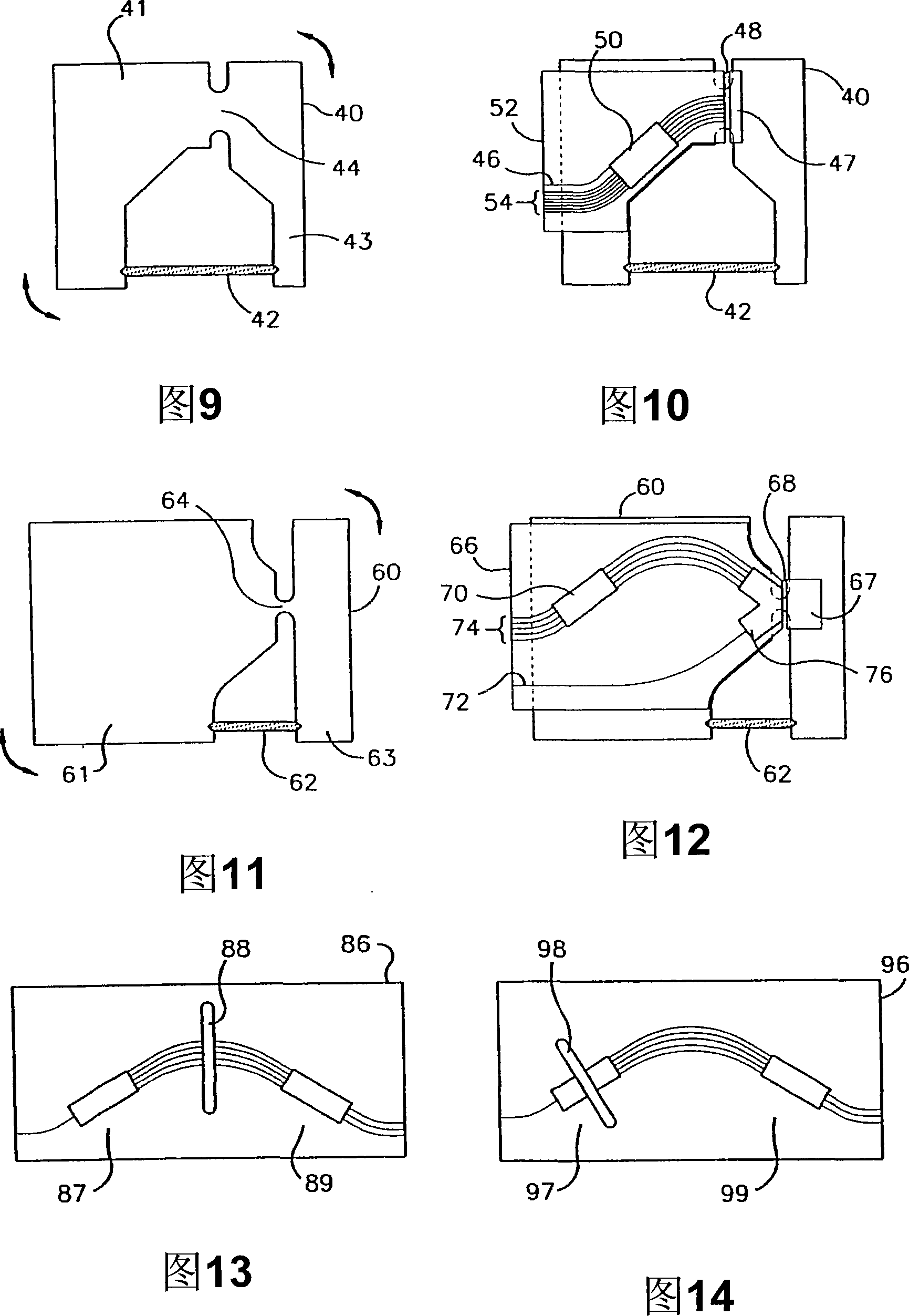
[0058] Various aspects of the invention will now be described with reference to the drawings, wherein like reference numerals are used to refer to like elements throughout. The present invention mitigates the temperature sensitivity of optical integrated circuits by employing mechanical beam steering.

[0059] The present invention provides an athermal OIC and an OIC with low power consumption by employing beam deflection, utilizing an OIC or AWG with two or more distinct regions or sheets that can move relative to each other. This relative movement results in a shift in the center wavelength (CW) of the OIC, or peak transmission wavelength for a given channel, proportional to the movement of the two plates. The OIC is designed such that the magnitude of the CW change caused by the motion of the two sheets is equal in magnitude to the CW change inherent in the OIC (which is caused by the expansion / contraction of the OIC and the dependence of the waveguide refractive index on t...


PUM

PropertyMeasurementUnit
Widthaaaaaaaaaa
Widthaaaaaaaaaa

Abstract

Optical integrated circuits are disclosed having a gap (18) traversing the lens or the waveguide grating and an actuator (12) that controllably positions the optical integrated circuit on each side of the gap (18). As a result, the thermal sensitivity of the optical integrated circuits, for example, arrayed waveguide gratings, is mitigated. Also disclosed are methods for fabricating optical integrated circuits employing the gap (18) and the actuator (12).

Description

technical field [0001] The present invention relates to the field of optical integrated circuits, and more particularly to apparatus and methods for providing arrayed waveguides with a temperature-independent center wavelength. Background technique [0002] Optical integrated circuits (OICs) come in many forms, such as 1xN optical splitters, optical switches, wavelength division multiplexers (WDMs), demultiplexers, optical add-drop multiplexers (OADMs), and others. These OICs are employed in building optical networks in which optical signals are transmitted between optical devices for carrying data. For example, traditional handshaking within telecommunications and data communication networks, in which electrical signals are transmitted via electrical conductors, is being replaced by optical fibers and light circuits, which transmit optical (eg, light) signals. These optical signals may carry data or other information through modulation techniques for transmission of such i...

Claims


Application Information

Patent Timeline
IPC IPC(8): G02B6/34G02B6/293G02B6/12
CPCG02B6/12011G02B6/12G02B6/12014G02B6/1203G02B2006/12135G02B2006/12159
Inventor R·科尔M·格雷罗K·珀切斯A·J·蒂克纳K·麦格里尔D·门彻P·D·阿斯卡尼奥
Owner NEOPHOTONICS CORP
Why Eureka
Try Eureka