Piezoelectric actuator
A technology of actuators and piezoelectric elements, applied in the directions of electrical components, piezoelectric devices/electrostrictive devices, piezoelectric/electrostrictive/magnetostrictive devices, etc., can solve the problem that the displacement characteristics of piezoelectric actuators cannot be fully solved. , large fluctuations, fluctuations and other issues
- Summary
- Abstract
- Description
- Claims
- Application Information
AI Technical Summary
Problems solved by technology
Method used
Image
Examples
Embodiment 1
[0270] Next, examples of the present invention will be described.
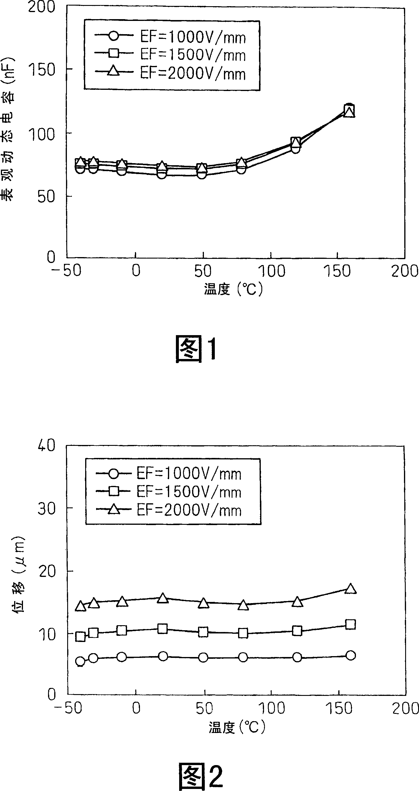
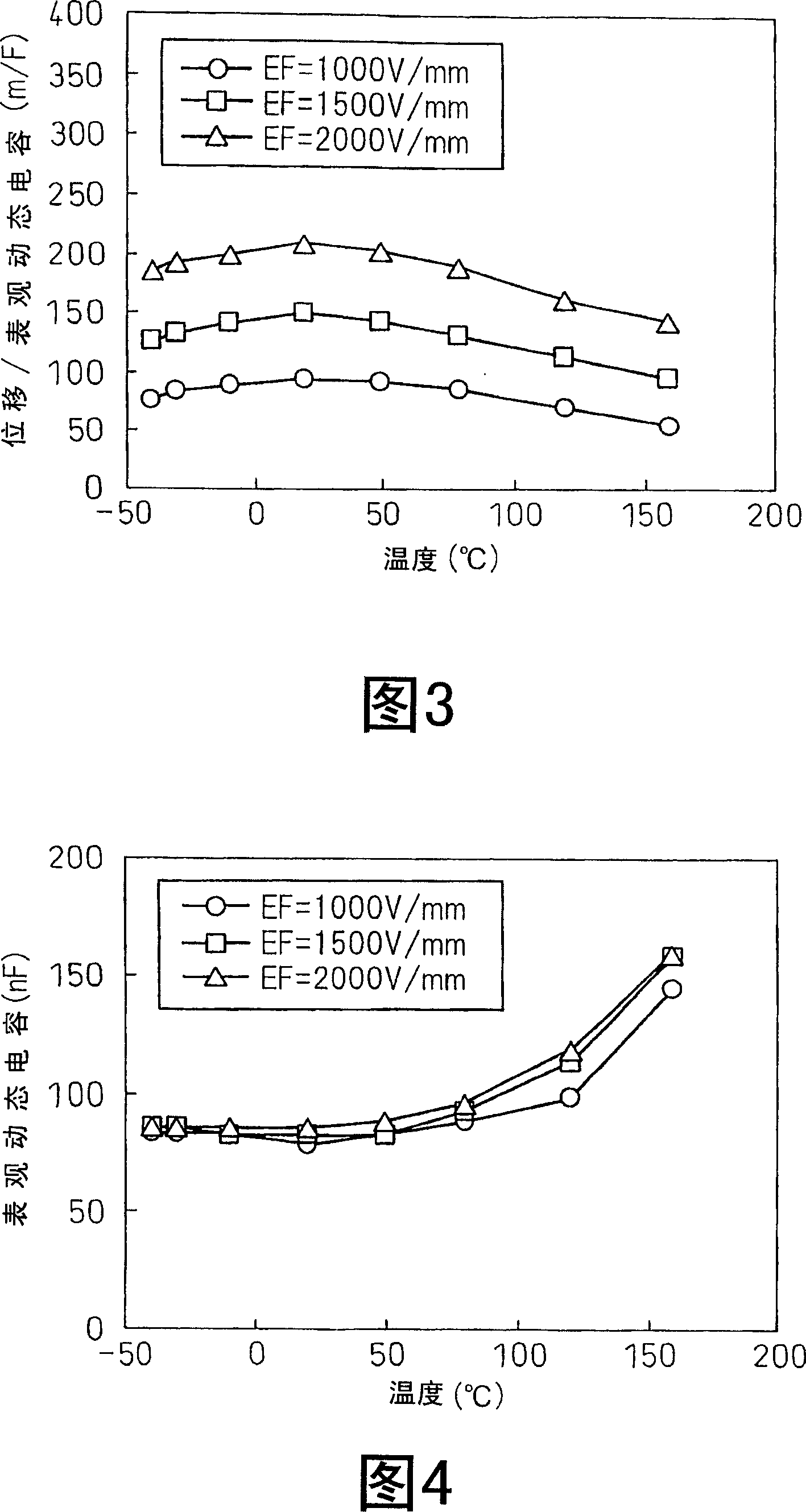
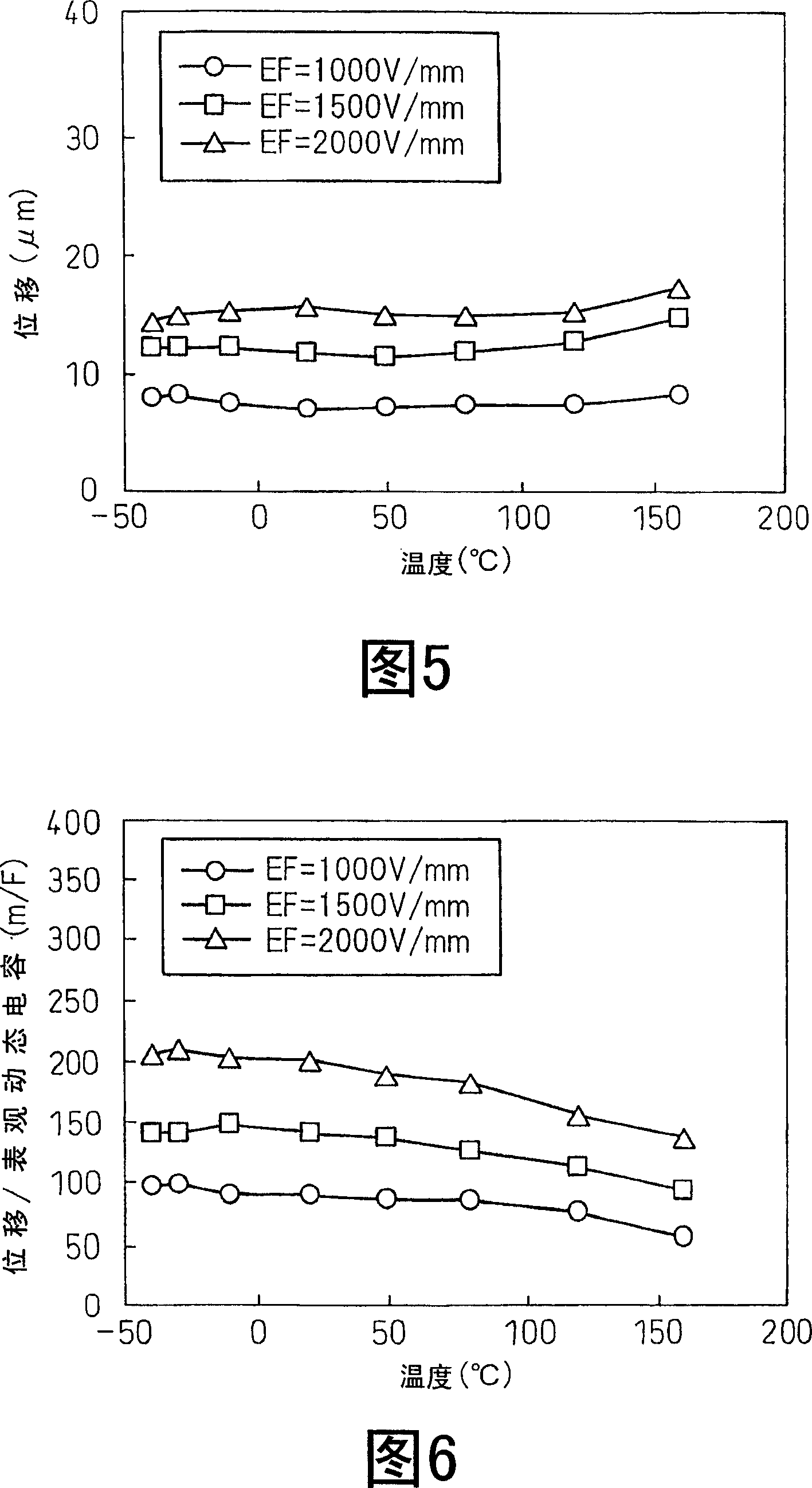
[0271] In this example, a piezoelectric element including piezoelectric ceramics was produced, and a piezoelectric actuator was produced using this piezoelectric element.
[0272] In this example, as a model of the piezoelectric actuator, a piezoelectric actuator 11 using a jig 8 is fabricated as shown in FIG. 37 .
[0273] That is, the piezoelectric actuator 11 of this example has a multilayer piezoelectric element 2 using piezoelectric ceramics as a driving source, and the piezoelectric element 2 is fixed by a jig 8 .
[0274]The jig 8 has a housing 81 for accommodating the piezoelectric element 2 , and a piston (connecting member) 82 connected to the piezoelectric element 2 and transmitting the displacement of the piezoelectric element 2 . Piston 82 is connected to guide 83 via disk spring 85 . A base portion 815 is provided inside the housing 81 , and the piezoelectric element 2 is arranged on the base p...
Embodiment 2
[0326] Except that the calcining temperature of the sheet-shaped molded body after degreasing is set to 1105°C, follow the same steps as in Example 1 to produce 0.07 (K 0.45 Na 0.55 ) 0.93}{Nb 0.82 Ta 0.10 Sb 0.08}O 3 Composition of crystal-oriented ceramics. With regard to the obtained crystal-oriented ceramics, the sintered body density, average orientation degree, and piezoelectric properties were evaluated under the same conditions as in Example 1. In addition, a laminated actuator of 40 piezoelectric elements was manufactured in the same procedure as in Example 1, and the characteristics of the actuator were evaluated.
[0327] The relative density of the crystal-oriented ceramics obtained in this embodiment is above 95%. In addition, the pseudo-cubic {100} planes are oriented parallel to the tape planes, and the average degree of orientation of the pseudo-cubic {100} planes measured by the Lautergelding method is 94.6%. Also, as a result of the evaluation of the...
Embodiment 3
[0342] Except that the calcining temperature of the sheet-shaped molded body after degreasing is set to 1105°C, follow the same steps as in Example 1 to produce 0.065 (K 0.45 Na 0.55 ) 0.935}{Nb 0.83 Ta 0.09 Sb 0.08}O 3 Composition of crystal-oriented ceramics. With regard to the obtained crystal-oriented ceramics, the sintered body density, average orientation degree, and piezoelectric properties were evaluated under the same conditions as in Example 1. In addition, a laminated actuator of 40 piezoelectric elements was produced in the same procedure as in Example 1, and the characteristics of the actuator were evaluated.
[0343] The relative density of the crystal-oriented ceramics obtained in this embodiment is above 95%. In addition, the pseudo-cubic {100} planes were oriented parallel to the tape planes, and the average degree of orientation of the pseudo-cubic {100} planes measured by the Lautergelding method was 93.9%. In addition, as a result of the evaluation...
PUM
| Property | Measurement | Unit |
|---|---|---|
| Curie temperature | aaaaa | aaaaa |
| The average particle size | aaaaa | aaaaa |
Abstract
Description
Claims
Application Information
 - R&D
- Intellectual Property
- Life Sciences
- Materials
- Tech Scout
- Unparalleled Data Quality
- Higher Quality Content
- 60% Fewer Hallucinations
Browse by: Latest US Patents, China's latest patents, Technical Efficacy Thesaurus, Application Domain, Technology Topic, Popular Technical Reports.
© 2025 PatSnap. All rights reserved.Legal|Privacy policy|Modern Slavery Act Transparency Statement|Sitemap|About US| Contact US: help@patsnap.com


