Control device

A control device and control quantity technology, applied to valve devices, control systems, electrical controls, etc., can solve problems such as the increase in the degree of estimated temperature change, the inability to properly estimate the temperature of the motor, and the increase in manufacturing costs.

A control device and control quantity technology, applied to valve devices, control systems, electrical controls, etc., can solve problems such as the increase in the degree of estimated temperature change, the inability to properly estimate the temperature of the motor, and the increase in manufacturing costs.

CN101019305AInactive Publication Date: 2007-08-15HONDA MOTOR CO LTD

Image

  • Control device
  • Control device
  • Control device

Examples


Embodiment Construction

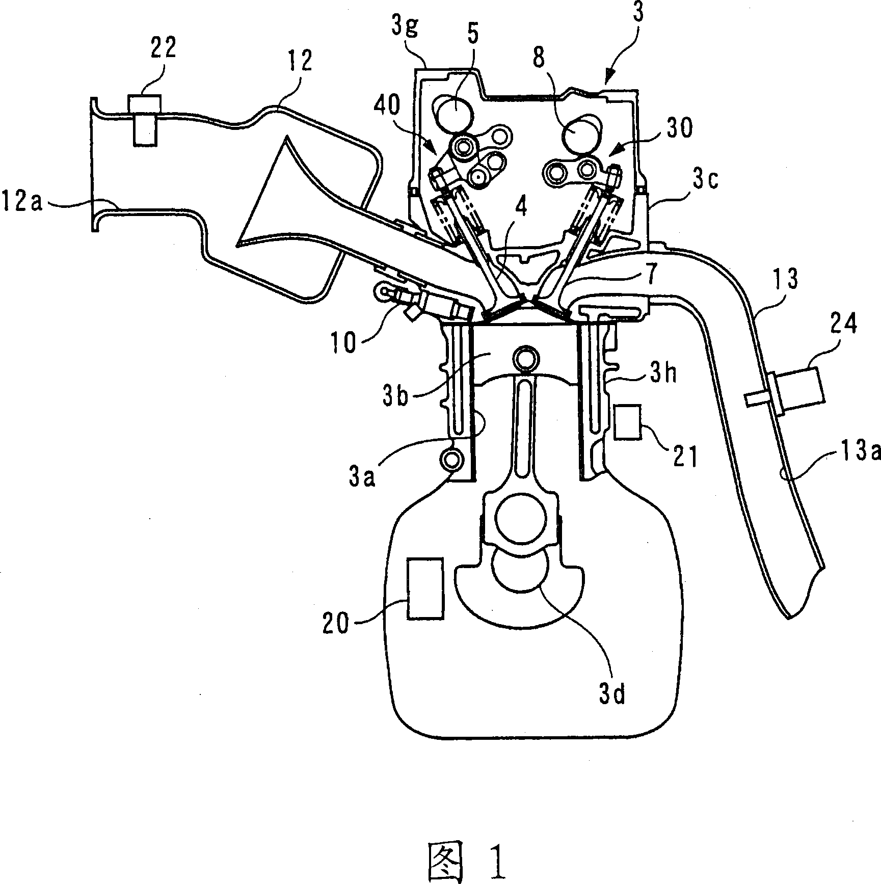
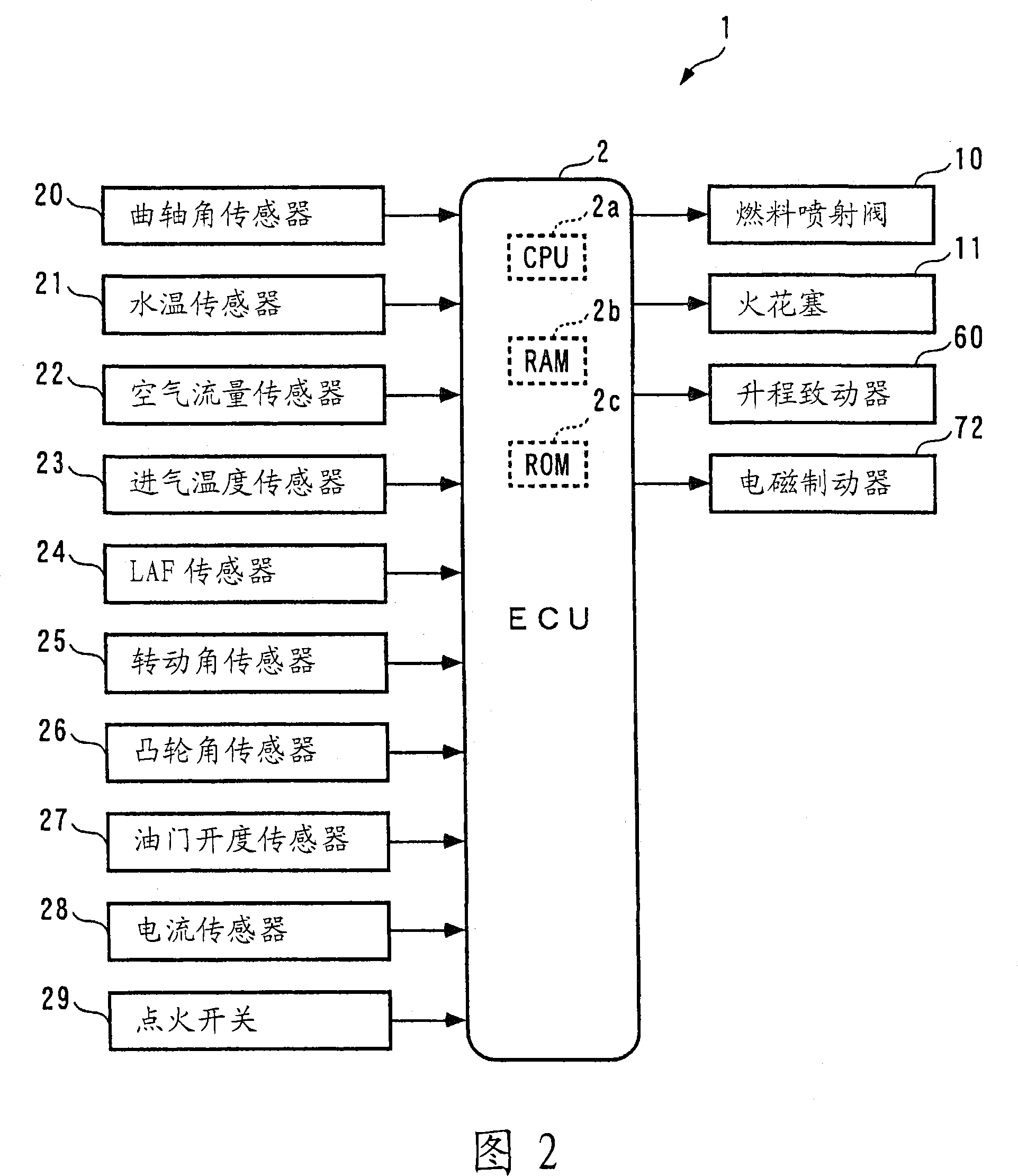
[0059] Next, a control device according to an embodiment of the present invention will be described with reference to the drawings. As shown in FIG. 2 , the control device 1 has an ECU 2 that executes variable mechanism control, fuel injection control, and ignition timing control, etc., in accordance with the operating state of an internal combustion engine (hereinafter referred to as "engine") 3 as described later. control processing.

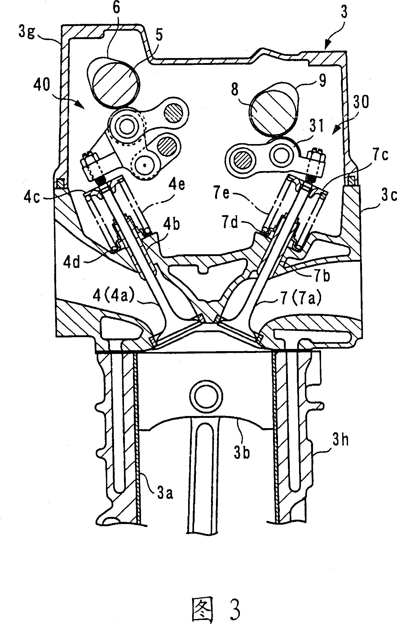
[0060] As shown in FIGS. 1 and 3 , the engine 3 is an inline four-cylinder DOHC gasoline engine having four sets of cylinders 3 a and pistons 3 b (only one set is shown), and is mounted on an unillustrated vehicle. The engine 3 has: an intake valve 4 and an exhaust valve 7 which are arranged on each cylinder 3 a and respectively open and close the intake port and the exhaust port, an intake camshaft 5 and an intake valve for driving the intake valve 4 . The gas cam 6, the variable intake valve driving mechanism 40 for opening and closing the ...


PUM


Abstract

The present invention provided a controller which capable of avoiding an overload state of an actuator without using a sensor and so forth. An ECU (2) of the controller (1) calculates a lift control input U_Liftin into a variable valve lift mechanism (50) according to an algorithm of formulae ((2) to (5)) so that the valve lift Liftin follows up a target valve lift Liftin_cmd, integrates the product of the value Imot of the current flowing through the variable valve lift mechanism (50) and the sampling period Stime to calculate the integrated value SImot. If SImot=SImot_J1, two parameters pole_f_lf, pole_lf are set to predetermined failure values pole_f_lf_J1, pole_lf_J1, respectively, at which the lift control input U_Liftin is smaller than that of when SImot<SImot_J1.

Description

technical field [0001] The present invention relates to a control device that controls a control amount by an actuator that converts supplied electric power into driving force. Background technique [0002] Conventionally, as a control device that controls an assist torque for assisting a driver's steering force through an electric power steering (electric power steering) as an actuator, a device described in Patent Document 1 is known. . The electric power steering system includes an electric motor that generates assist torque, and the control device includes a thermistor that detects the temperature of the electric motor, a vehicle speed sensor that detects the vehicle speed, and the like. [0003] This control device controls the assist torque by determining a voltage applied to the motor based on the temperature of the motor detected by the thermistor and the vehicle speed detected by the vehicle speed sensor, thereby controlling the assist torque. First, the temperatu...

Claims


Application Information

Patent Timeline
15 Aug 2007
Publication
CN101019305A
IPC
H02P29/00; F02D13/02; G05B13/02; F01L13/00; F01L1/352; F02D45/00; H02P29/02
CPC
F02D2041/2048; F02D2041/1422; Y02T10/18; Y02T10/40; G05B13/021; F02D35/0007; F02D2041/2058; F02D41/221
Inventors
下城孝名子; 安井裕司