Positive-rotating rotary tillage straw-burying method

A technology of straw and forward rotation, which is applied in the directions of tillage tools, crop processors, cutters, etc., can solve the problems of increased resistance, low productivity, and inability to use reverse stubble cutters.

Inactive Publication Date: 2007-08-29
TAIZHOU JIANGYAN XINKE MACHINERY MFG CO LTD
View PDF2 Cites 6 Cited by
  • Summary
  • Abstract
  • Description
  • Claims
  • Application Information

AI Technical Summary

Problems solved by technology

However, the problem caused by the reversal of the cutter shaft is that the resistance of the cutter when cutting the soil increases, which increases the power consumption of the tractor, and the productivity is low. Taking a 50-horsepower tractor as an example, it can only drive a reverse stubble cutter with a width of 1.7 meters. The operation is 3-4 mu per hour, and the reverse stubble cutter cannot be used for straw returning in paddy fields

Method used


Image

  • Positive-rotating rotary tillage straw-burying method
  • Positive-rotating rotary tillage straw-burying method
  • Positive-rotating rotary tillage straw-burying method

Examples


example 1

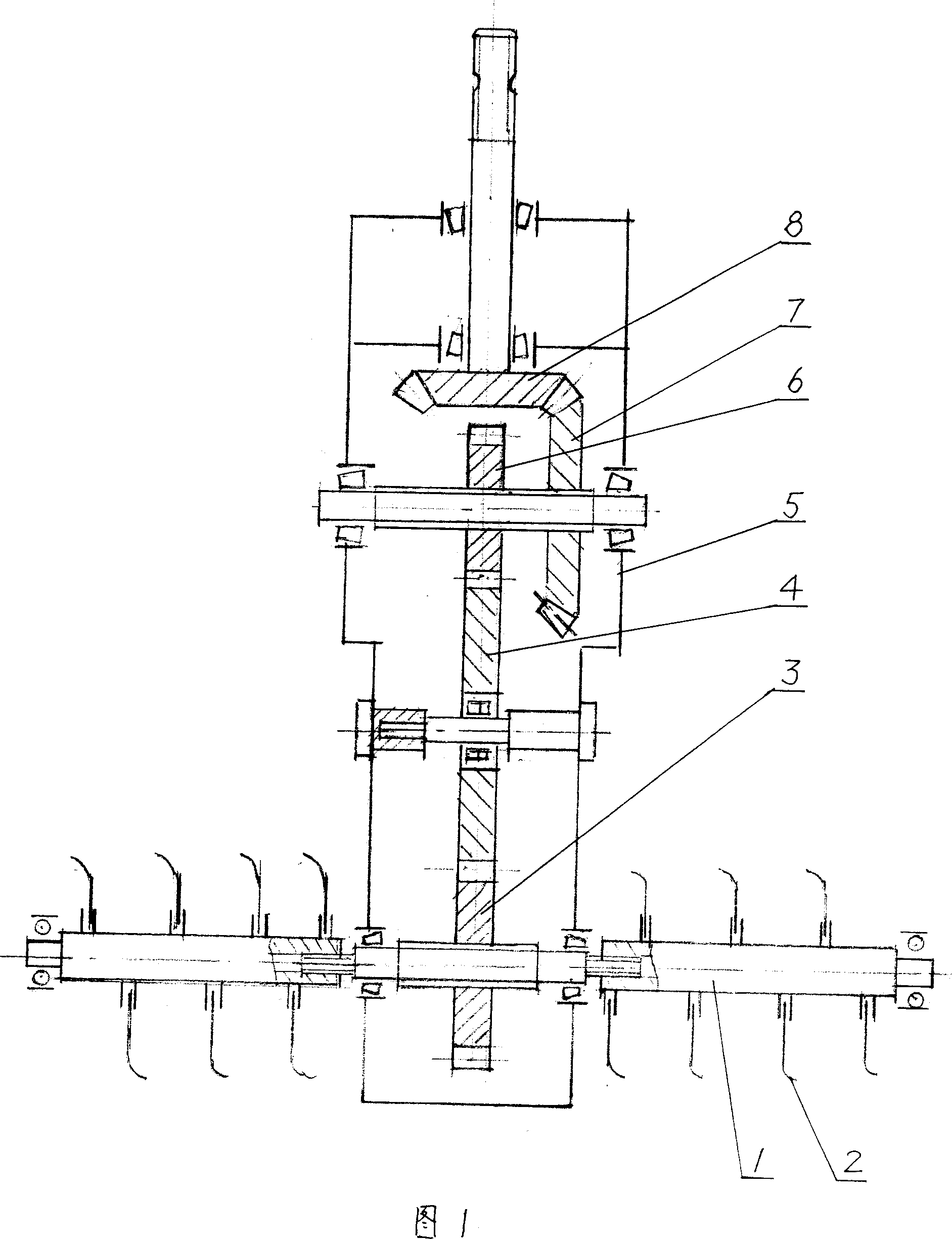
[0011] Example 1: See Fig. 1, the transmission mode combining one-stage bevel gear deceleration and one-stage spur gear deceleration is adopted between the cultivator cutter shaft 1 and the power input shaft, and the transmission mechanism is all set in the middle box body 5 of the tillage machine Inside, the number of teeth of the bevel gears 8 and 7 are 19 and 35 respectively, the number of teeth of the spur gears 6 and 3 are 17 and 19 respectively, there is an intermediate gear 4 between the two spur gears, and the speed of the tractor power output shaft is n 1 =720 rev / min, then the cutter shaft 1 speed n 2 = 720 × 19 35 × 17 19 = 350 rev / min, knife The shaft rotates in the forward direction, and the stubble knife 2 digs up the straw and the soil together when cutting the soil at high speed, stirs and ...

example 2

[0012] Example 2: See Figure 1, the number of teeth of the bevel gears 8 and 7 are 21 and 33 respectively, the number of teeth of the spur gears 6 and 3 are 15 and 19 respectively, the speed of the power output shaft is n 1 =720 rev / min, cutter shaft 1 speed n 2 =362 revs / min, all the other expressions are as example 1.

example 3

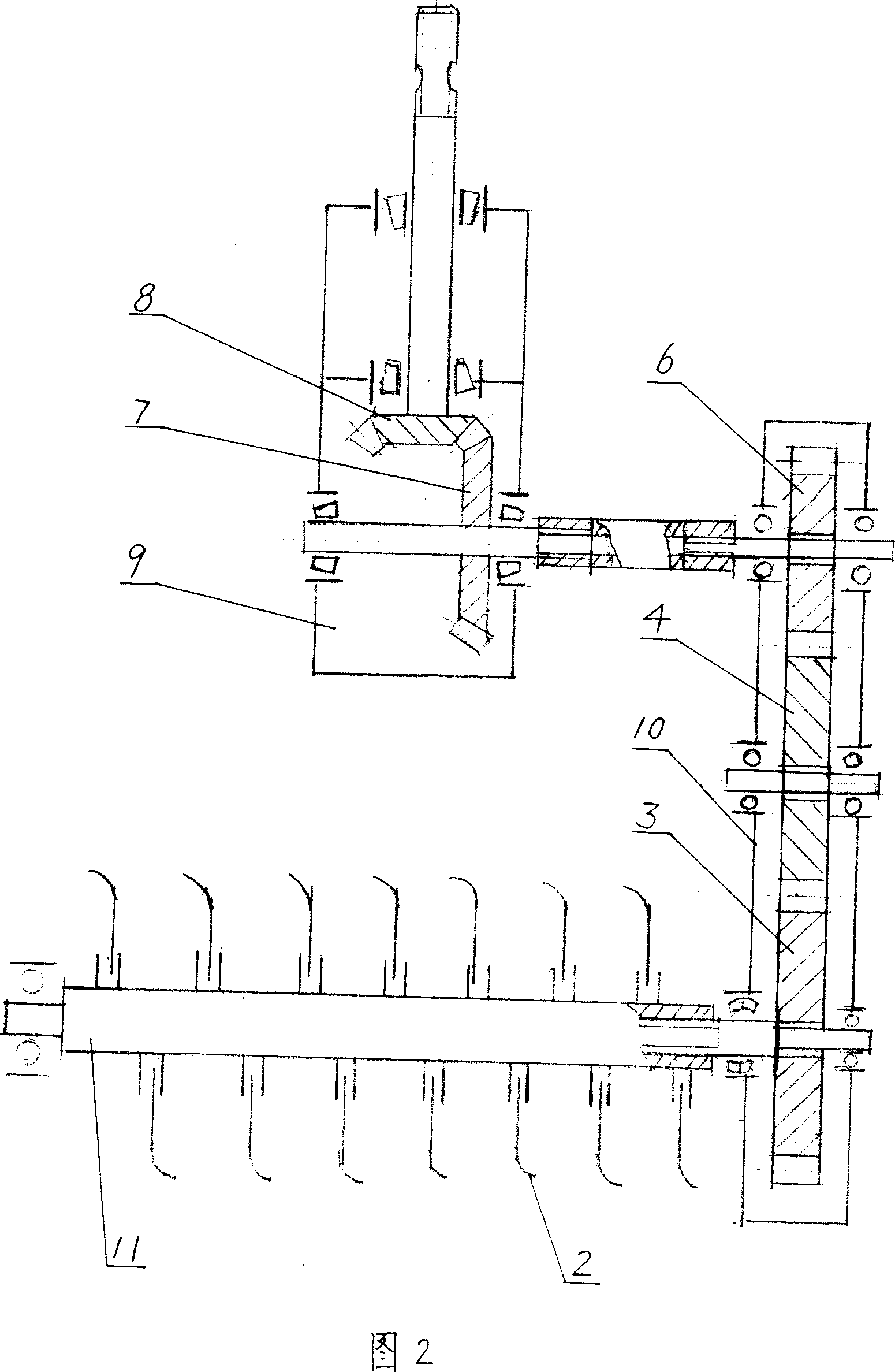
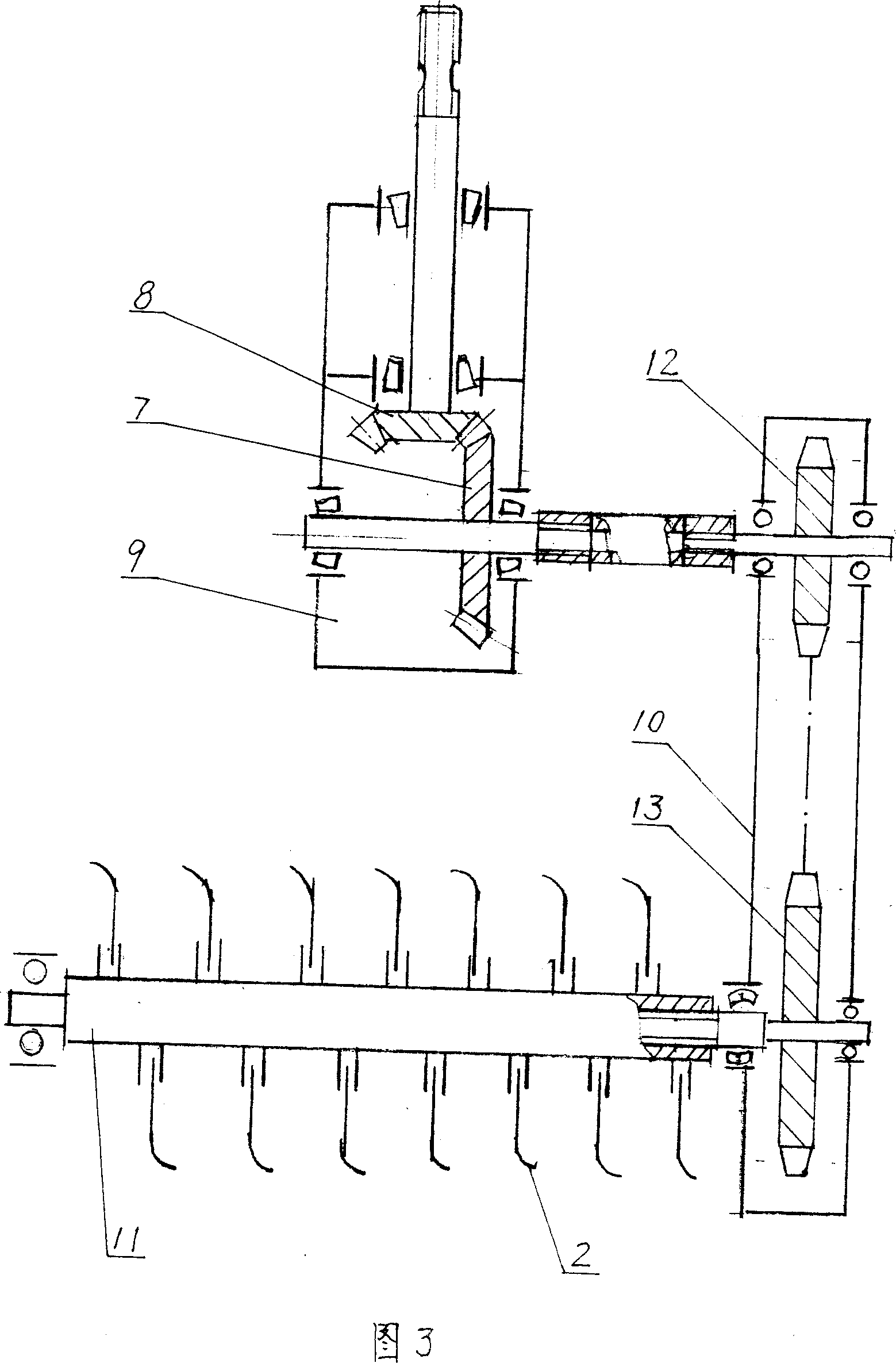
[0013] Example 3: See Figure 2, the bevel gear reduction mechanism in the transmission mechanism is arranged in the middle box 9, and the spur gear reduction mechanism is arranged in the side box 10, wherein the number of teeth of the bevel gears 8 and 7 are 21 and 33 respectively, The number of teeth of the spur gears 6 and 3 are 16 and 19 respectively, and the rotational speed of the power output shaft is n 1 =780 rpm, cutter shaft 11 speed n 2 =417 revs / min, all the other expressions are as example 1.


PUM


Abstract

The present invention relates to a forward-rotating rotary cultivation whole straw mulch-durying method. It is mainly characterized by that it utilizes the rotation of rotary tiller blade shaft to drive stubble-burying blade to mulch-bury the straw. Said blade shaft is forwards rotated, and its rotating speed is 340-500 rpm, and its drive mechanism adopts reduction drive mode of gear drive or gear and chain drive. Besides, said invention also provides the concrete operation steps of said method.

Description

technical field [0001] The invention relates to a method for returning straws to the field in the agricultural cultivation technology, in particular to a method for covering and returning the straw in full amount to the field by using tillage machinery. Background technique [0002] Straw returning to the field is of great significance for saving resources, protecting the environment, developing ecological agriculture, and building a new socialist countryside, and has been paid more and more attention to and researched by people. There are multiple methods for straw returning to the field, among which, it is quite effective and worthy of popularization to use plowing machinery to cover and embed the harvested and cut straw in the soil while plowing the land. At present, when the existing stubble tillage machinery (patent number: 200420028055.5 and patent number: 200620070527.2) works, the cutter shaft adopts the forward rotation mode, that is, the rotation direction of the c...

Claims


Application Information

Patent Timeline
Patent Type & Authority Applications(China)
IPC IPC(8): A01B33/08A01B43/00A01B71/06A01D82/00
Inventor 史孝华钱树培
Owner TAIZHOU JIANGYAN XINKE MACHINERY MFG CO LTD
Why Eureka
Try Eureka