Storied-building board energy-eliminating shock-insulating structure

A floor and energy-dissipating technology, which is applied in the direction of floors, earthquake resistance, and building components, can solve the problems of increased housing cost, large building space, and occupancy, and achieve the effects of enhancing the ability to consume earthquake energy, increasing initial stiffness, and flexible layout

Inactive Publication Date: 2007-08-29
GUANGZHOU UNIVERSITY
View PDF4 Cites 19 Cited by
  • Summary
  • Abstract
  • Description
  • Claims
  • Application Information

AI Technical Summary

Problems solved by technology

Therefore, in order to achieve a better energy dissipation effect, it is necessary to install a large number of energy dissipation dampers in the structural system of the house, which will increase the cost of the house more.
In addition, most of the existing energy-dissipating components are in the form of energy-dissipating supports or energy-dissipating shear walls, which occupy a large building space and make owners less willing to adopt energy-dissipating and shock-absorbing technologies

Method used


Image

  • Storied-building board energy-eliminating shock-insulating structure
  • Storied-building board energy-eliminating shock-insulating structure
  • Storied-building board energy-eliminating shock-insulating structure

Examples


example 1

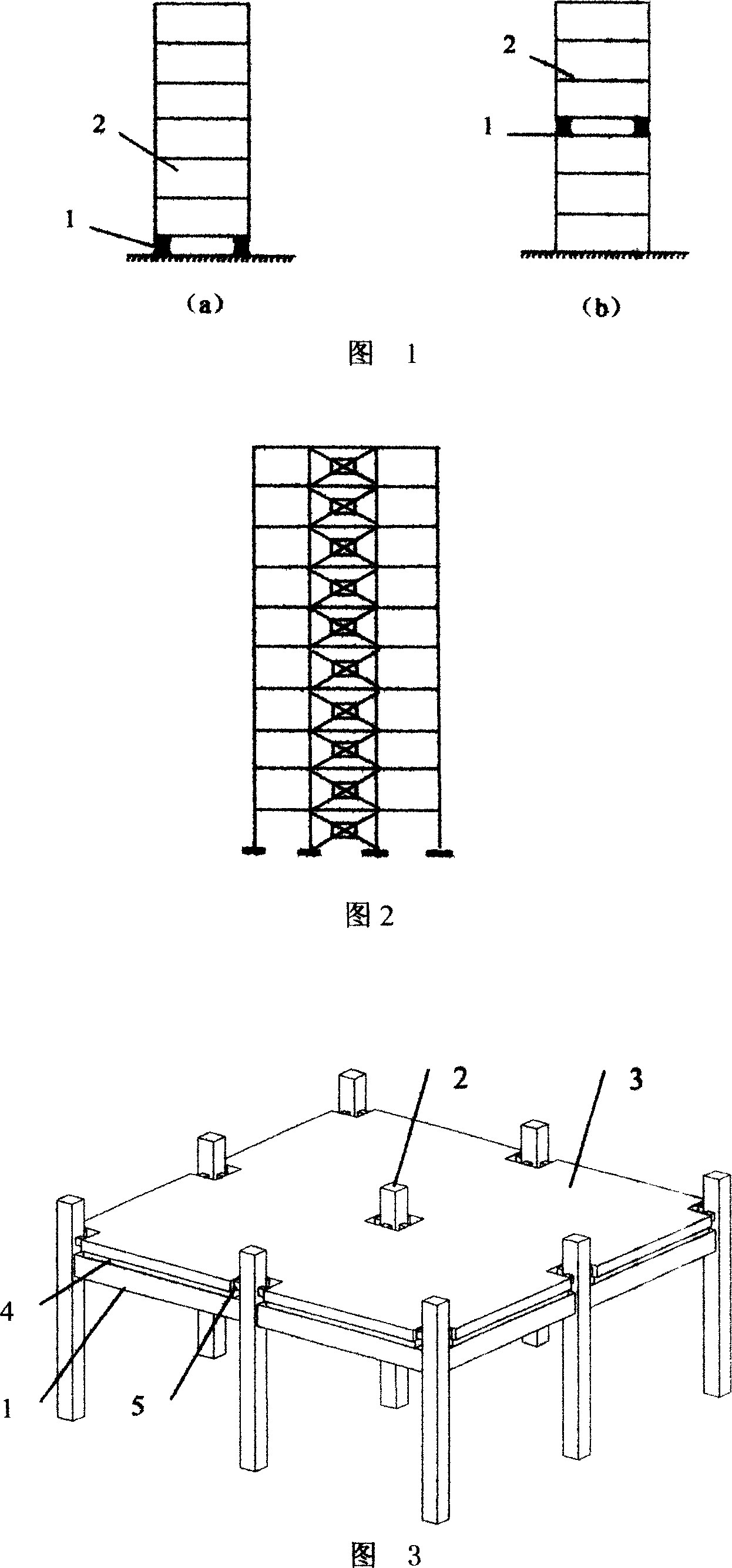
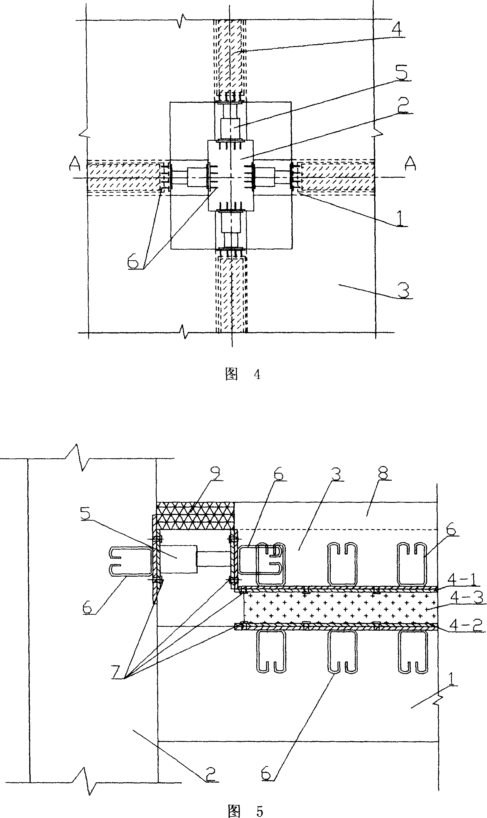
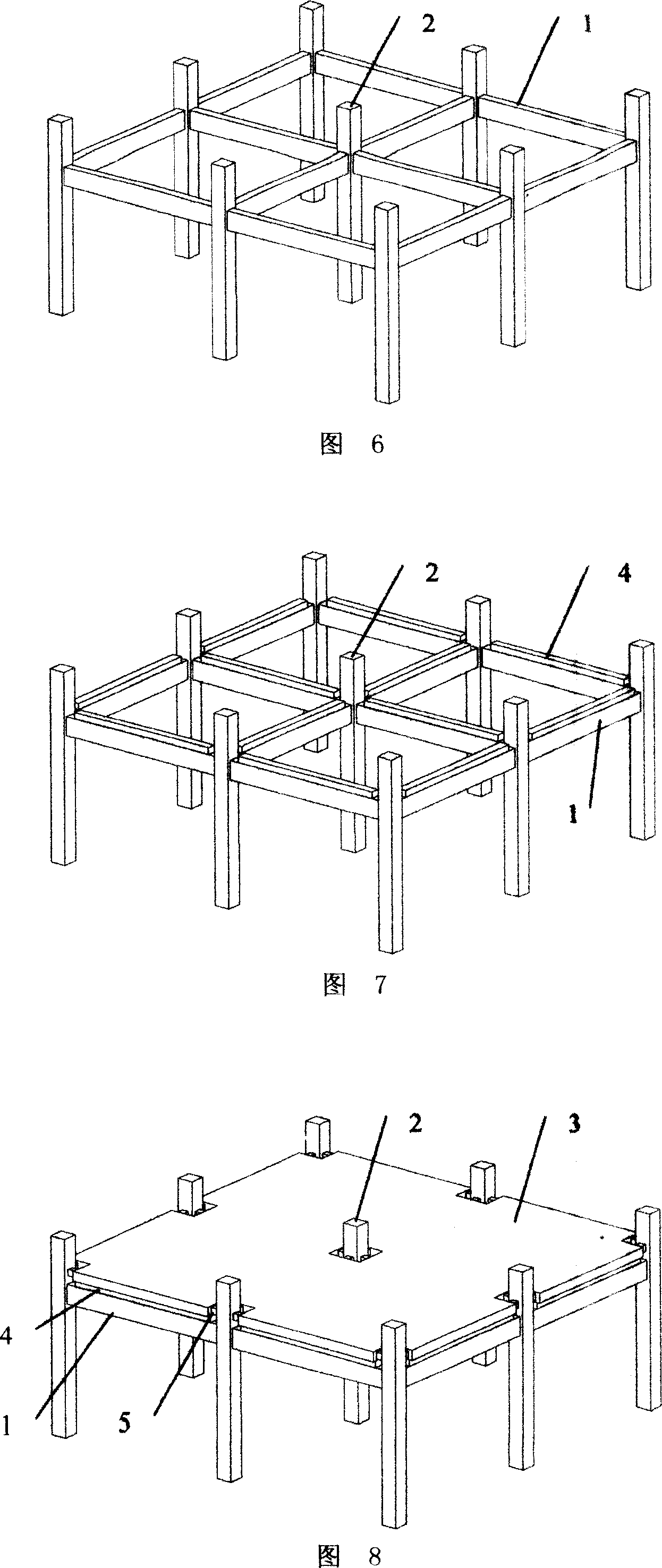
[0047] Referring to Fig. 3, Fig. 4 and Fig. 5, this embodiment is an energy-dissipating and seismic-isolation structure between a floor slab and a reinforced concrete frame beam-column. A damping and shock-isolation layer 4 is provided between the floor 3 and the concrete beam 1 , and an energy dissipation damper 5 is provided between the end face of the floor 3 and the concrete column 2 . Among them, the connecting parts of the concrete beam 1, the floor 3 and the damping and isolation layer 4 are all provided with a connecting piece 6, and the connecting piece 6 uses bolts 7 to connect the concrete beam 1, the floor 3 and the damping and isolating layer 4 into one The connecting part of the concrete column 2 and the end surface of the floor 3 is also provided with a connector 6, and the energy dissipation damper 5 is connected to the connector 6 to connect the concrete column 2 and the floor 3 into one. The damping and isolation layer 4 described in this example is made of l...

example 2

[0055] Referring to Fig. 9, Fig. 10, Fig. 11 and Fig. 12, this embodiment is an energy-dissipating and seismic-isolation structure between a floor slab, a reinforced concrete frame beam column and a shear wall, and the energy-dissipating and seismic-isolation structure is constituted as follows: Concrete beams 1, columns 2, a cylinder surrounded by shear walls 2a, and concrete secondary beams 1' spanning between the two concrete beams 1 form the main structure. Each room is provided with a damping and isolation layer 4, and an energy dissipation damper 5 is provided between the end face of the floor 3 and the concrete column 2 and the shear wall 2a. Among them, the connecting parts of the concrete secondary beam 1', the floor 3 and the damping and isolation layer 4 are provided with connectors 6, and the concrete beam 1', the floor 3 and the damping and isolation layer 4 are connected by the connectors 6 with bolts 7. Linked into one; the concrete column 2, the connecting part...

example 3

[0059] Referring to Fig. 13, in the embodiment described in Example 1 (or Example 2), only a gap 13 may be left between the floor 3 and the vertical load-bearing member (column 2 or shear wall 2a), so that the floor 3 and the vertical Complete isolation from load-bearing members. If this floor is inhabited, described gap 13 also does not need sealing. Other structures of this embodiment can be implemented with reference to Example 1 or Example 2.


PUM


Abstract

The invention discloses a floorslab energy eliminating vibration isolating structure, comprising floorslab and vertical and horizontal weight bearing components of main structure, characterized in that: an damping vibration isolating layer is arranged between the floorslab and the horizontal weight bearing component and air gaps are arranged between the floorslab and the vertical weight bearing component, where the damping vibration isolating layer is composed of low-hardness, high-damping rubber arranged between the upper and lower connecting plates, and interconnected with the horizontal weight bearing component and the floorslab. And the invention takes energy elimination as the principal thing, and has a certain vibration isolating function, and has advantages of simple and convenient to construct, high energy eliminating efficiency, and occupying no building space. And the invention can be used to reduce horizontal and vertical vibrations.

Description

technical field [0001] The invention relates to a building structure, in particular to an energy-dissipating and shock-isolation structure between a floor slab and a vertical load-bearing component and a horizontal load-bearing component. Background technique [0002] Earthquake is a sudden and devastating natural disaster. When an earthquake occurs, ground vibrations cause the seismic response of the structure. For a building structure whose foundation is consolidated on the ground, it is like an "amplifier" of ground seismic response. The seismic response of the structure is amplified layer by layer along the height from bottom to top. Expensive instruments and equipment in the room are damaged or other secondary disasters occur, and the main load-bearing structure is seriously damaged or even collapsed. [0003] At present, the traditional anti-seismic method commonly used in my country and other countries in the world is to properly control the stiffness of the structu...

Claims


Application Information

Patent Timeline
Patent Type & Authority Applications(China)
IPC IPC(8): E04B5/00E04B1/98E04B5/43E04B1/19E04H9/02
Inventor 冼巧玲
Owner GUANGZHOU UNIVERSITY
Why Eureka
Try Eureka