
Plasma display device

A plasma display and panel technology, applied to static indicators, instruments, solid cathode components, etc., can solve problems such as complexity, increased cost of plasma displays, and complicated processes

Inactive Publication Date: 2007-08-29
LG ELECTRONICS(NANJING) PLASMA CO LTD
View PDF0 Cites 1 Cited by
  • Summary
  • Abstract
  • Description
  • Claims
  • Application Information

AI Technical Summary

Problems solved by technology

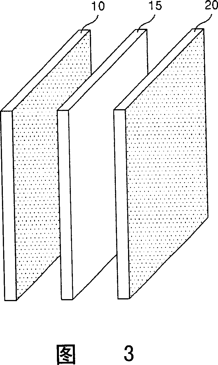
As a result, the traditional plasma display manufacturing process becomes somewhat complicated because of the addition of the heat dissipation layer 15 process.
In addition, while the process is complicated, the cost of plasma display manufacturing also increases, and the thickness of the panel also increases.

Method used


Image

  • Plasma display device
  • Plasma display device
  • Plasma display device

Examples


Embodiment Construction

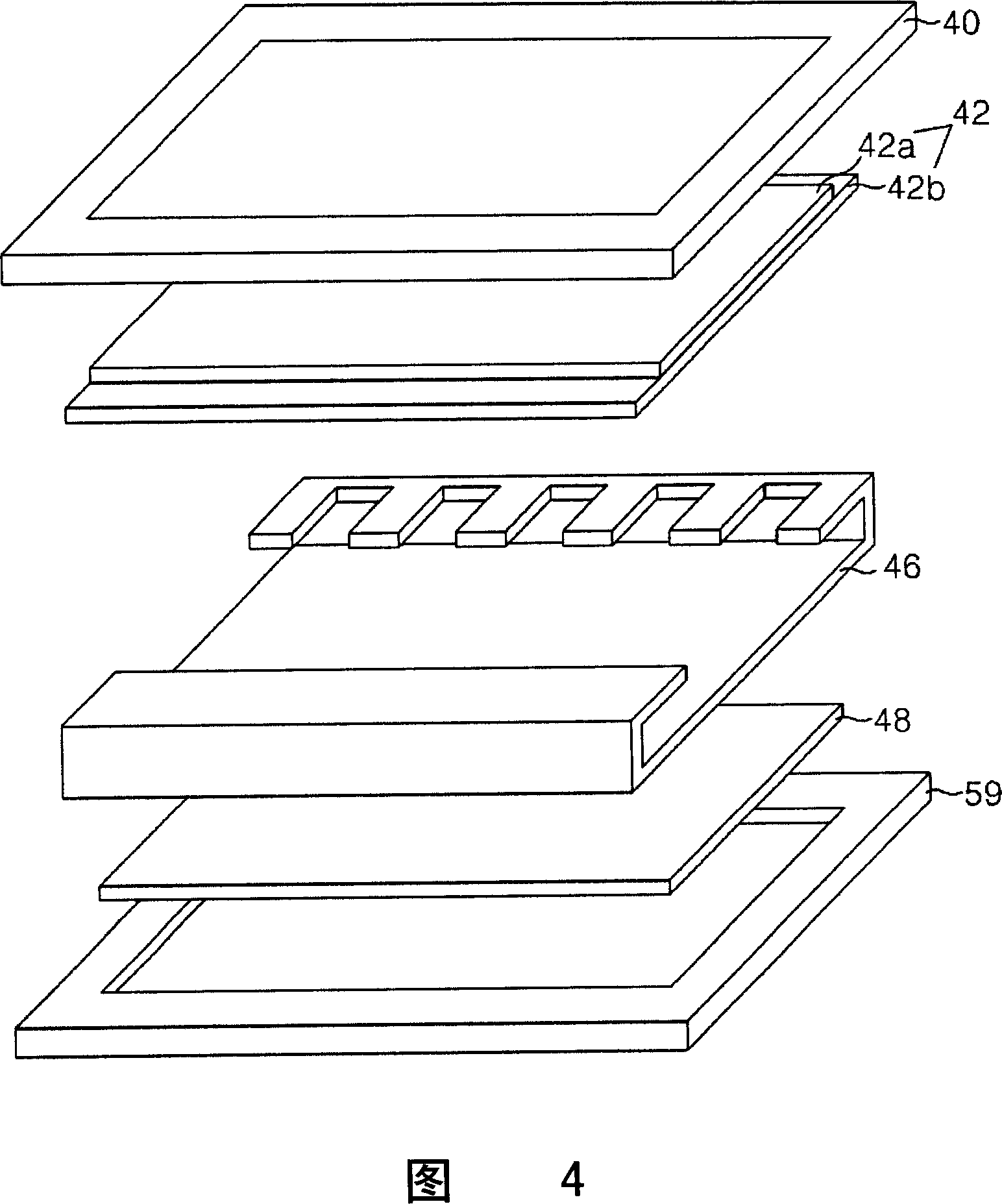
[0042] Hereinafter, referring to FIG. 4 to FIG. 10, an embodiment of the plasma display of the present invention will be described in detail.

[0043] FIG. 4 is a schematic diagram of a PDP according to the first embodiment of the present invention. FIG. 5 is a schematic diagram of a more detailed FPC connection form than the rack in FIG. 4 .

[0044] Referring to FIGS. 4 and 5 , the PDP according to the present invention is composed of a housing 40 , a panel 42 , a printed circuit board (PCB) 48 , a rear cover 59 and a frame 46 .

[0045] Frame (or radiating plate) 46) supports panel 42, when fixing PCB48, discharges the heat that panel 42 and PCB48 produce when driving, plays a heat release effect, prevents the phenomenon that the temperature of panel 42 and PCB48 rises sharply. Therefore, the frame 46 is made of a metal with good thermal conductivity, and aluminum (Al) is typically selected. In addition, the frame 46 can also use plastic materials that are easy to shape a...


PUM


Abstract

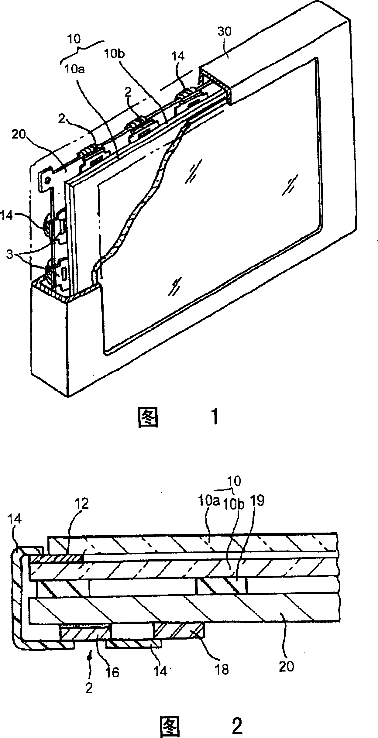
This invention relates to a plasma display including: an upper base board forming an upper electrode, a lower base board forming a lower electrode and a display panel with multiple discharge units between the upper and lower base boards, a flange surrounding the side of the panel and part of the front and a back frame of the bottom opposite to the back of the panel, and the heat releasing board is adhered to the panel without heat releasing layer.

Description

technical field [0001] The present invention relates to the technology of the plasma display, and more particularly, to the plasma display equipped with a heat radiation plate attached directly to the panel for protecting the panel. Background technique [0002] Recently, various flat panel displays that can reduce the disadvantages of Cathode Ray Tubes, ie, weight and volume, are being continuously developed. Flat panel displays can be classified into liquid crystal displays (Liquid Crystal Display: LCD), field emission displays (Field Emission Display: FED), plasma displays (Plasma Display Panel: hereinafter referred to as "PDP"), and electroluminescent displays (Electro-Luminescence: EL). )Wait. [0003] Among them, PDP is a flat-panel display that uses plasma discharge to display images. It has a fast response speed and is suitable for large-area image display, so it is widely used in high-definition televisions, monitors, and indoor advertising displays. [0004] FIG....

Claims


Application Information

Patent Timeline
IPC IPC(8): H01J17/49H01J17/16H01J17/02G09G3/28
Inventor 金德洙李炳喆孔俊熙
Owner LG ELECTRONICS(NANJING) PLASMA CO LTD
Learn More