Hot air gun circuit device and its working method

A circuit device and heat gun technology, applied in electric heating devices, electrical components, induction heating, etc., can solve problems such as non-conformity, inaccurate temperature adjustment, interference, etc., and achieve improved control accuracy, simple and convenient operation, and stable and reliable work. Effect

Inactive Publication Date: 2007-08-29
常州市英杰工具有限公司
View PDF3 Cites 20 Cited by
  • Summary
  • Abstract
  • Description
  • Claims
  • Application Information

AI Technical Summary

Problems solved by technology

[0007] The disadvantage of the heat gun of the prior art above is that the adjustment of the working temperature of the heat gun is realized by the potentiometer, and the user can only adjust the position of the potentiometer according to practical experience to set its corresponding working temperature. Therefore, the actual working temperature value is often difficult to grasp; at the same time, in the process of use, the temperature regulation circuit is affected by the temperature characteristics of the circuit components, making the working temperature of the heating element unstable, thus increasing the difficulty of temperature control
The disadvantage of this device is that the potentiometer is still used to set the working temperature of the heating element, and no compensation measures are taken at the cold end of the thermocouple, resulting in a large error, so it is not suitable for occasions with high temperature control requirements.
The disadvantage of this device is that the temperature display circuit in this device is a digital tube circuit composed of light-emitting diodes, and the normal operating temperature range of the heat gun is 130°C to 650°C, and only a few light-emitting diodes are used to display the current operating temperature. Its display error often reaches about 50°C
Secondly, no compensation measures are taken at the cold junction of the thermocouple, so the detection error often reaches about 20°C
Again, the device still uses a potentiometer to adjust the heating power of the heating element, and the temperature adjustment is not accurate
Therefore, the device is not suitable for occasions with high temperature control requirements.
[0010] In addition, when the heat gun in the above prior art is used, it is easy to generate interference signals to the outside, which is not conducive to the normal use of other electrical appliances, and does not meet the relevant standards of the European market.

Method used


Image

  • Hot air gun circuit device and its working method
  • Hot air gun circuit device and its working method
  • Hot air gun circuit device and its working method

Examples


Embodiment 1

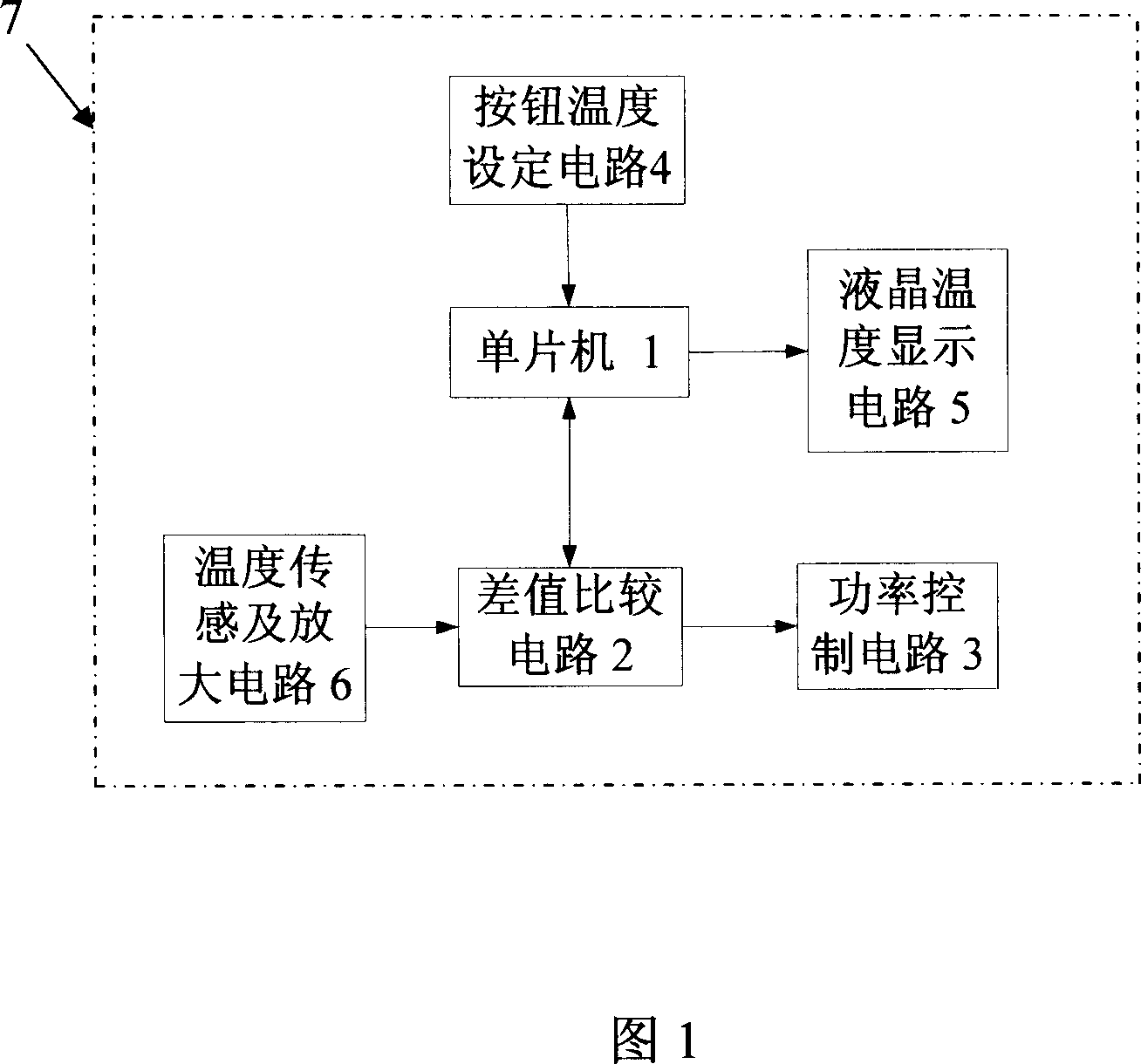
[0020] See Fig. 1, the circuit device of the heat gun of the present embodiment, comprise power supply circuit 8, the temperature control circuit 7 that links to each other with power supply circuit 8 and blower motor, be provided with wind wheel on the blower motor, heating element and temperature control circuit 7 connected.

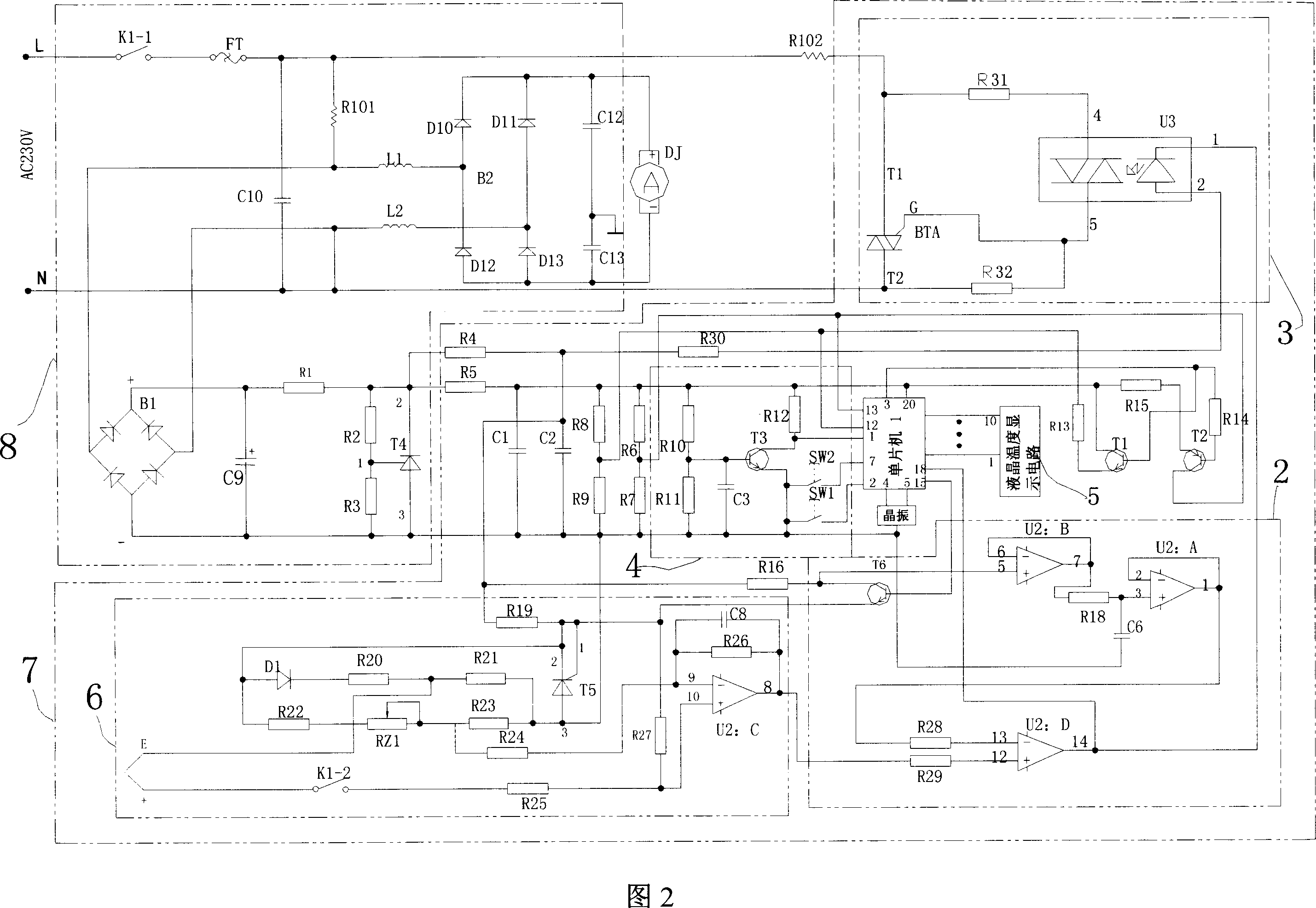
[0021] As shown in FIG. 2 , the power supply circuit 8 includes a switch K1 - 1 , a fuse FT, a drop resistance wire R101 , a filter capacitor C10 , a first rectification circuit and a second rectification circuit. The city alternating current is connected to the AC input terminals of the first rectification circuit and the second rectification circuit through the step-down resistance wire R101; the first rectification circuit is connected to the power supply terminal of the temperature control circuit 7, and the second rectification circuit is connected to the power supply terminal of the blower motor . The first rectification circuit includes a recti...


PUM


Abstract

The circuit device includes power supply circuit, temperature control circuit, blast motor, and heating element. The temperature control circuit includes single chip, power control circuit, temperature sensing and amplifying circuit (TSAC), button circuit for setting up temperature, LCD circuit for temperature, and difference value comparator circuit (DVCC). Based on signal of temperature setting value from the button circuit for setting up temperature, the single chip controls heating power of heating element, and sends signal of temperature setting value to LCD circuit for temperature to display temperature setting value. Comparing signal of working temperature of heating element measured by TSAC with temperature control signal from single chip, DVCC carries out comparison of difference value to generate signal of difference value.

Description

technical field [0001] The invention relates to a circuit device of a hot air gun and a working method thereof. The hot air gun is a heating tool used in industries such as electrical appliances, machinery, and plastic elbows. Background technique [0002] Existing hot air guns are all heated by heating elements when in use, and the fan blades are driven by the motor to rotate, and the hot air in the gun body is sent out. It is commonly used for removing paint, bending plastic pipes, welding metal pipe joints and heating certain surfaces. [0003] Chinese patent document CN2590663 discloses a heat gun, which includes a housing, and a motor installed in the housing, fan blades, heating elements, and air ducts. The heating wire of the heating element is coiled on a porcelain plate with a central hole. There are limited projections on the air outlet, which are arranged on the air duct cover of the air outlet. The limit projections can be three raised points or discs to ensure ...

Claims


Application Information

Patent Timeline
IPC IPC(8): H05B1/00H05B6/06G05D23/00F24H3/00F24H9/00
Inventor 焦富成
Owner 常州市英杰工具有限公司
Why Eureka
Try Eureka