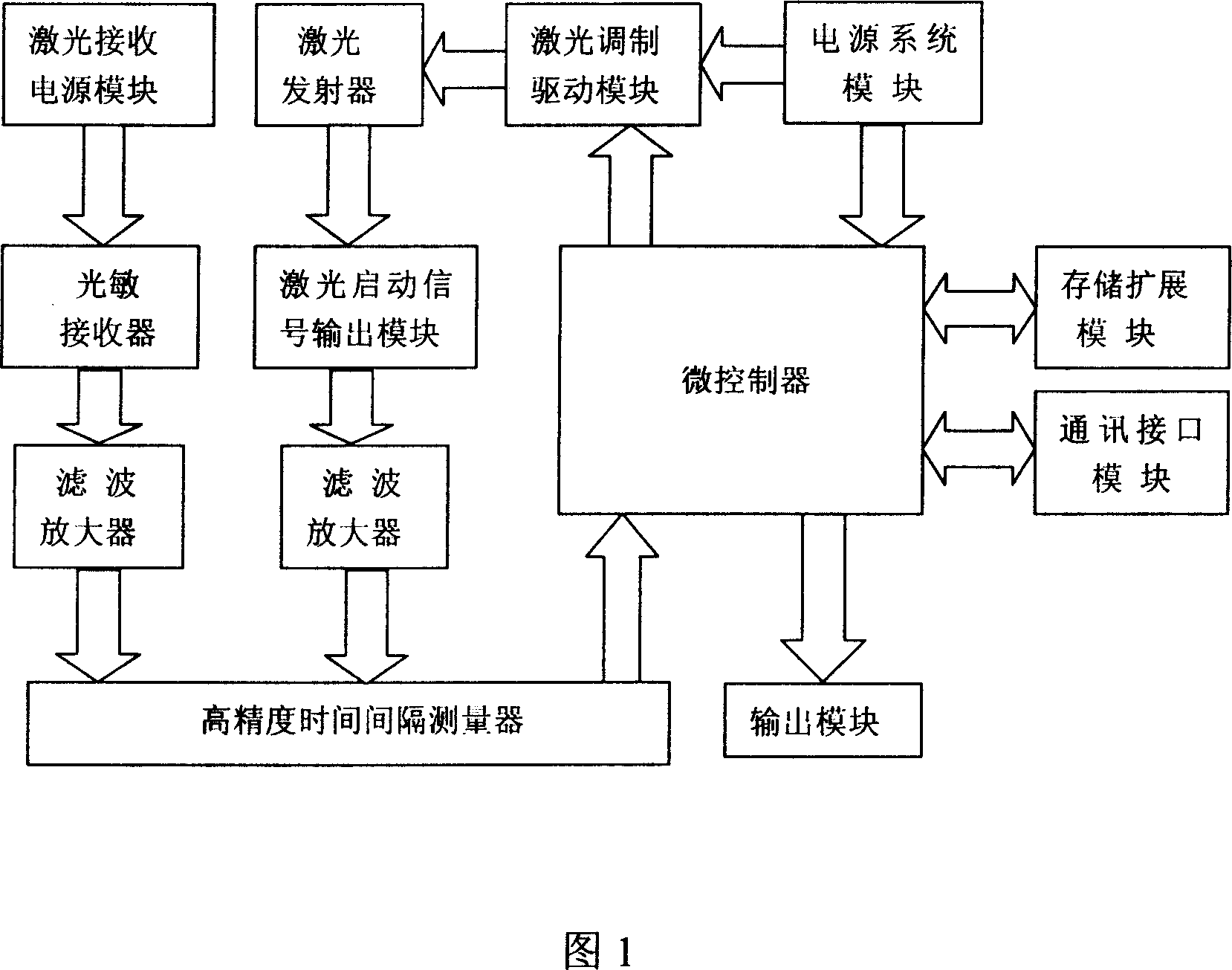
High-precision laser range-finding device

A laser ranging, high-precision technology, applied in the direction of measuring devices, radio wave measuring systems, electromagnetic wave re-radiation, etc., can solve the problem of unsatisfactory ranging accuracy and anti-interference effects, and unreasonable component selection and configuration and other problems, to achieve the effect of short measurement time, strong anti-interference ability and high measurement accuracy

Inactive Publication Date: 2007-09-05
上海派恩科技有限公司
View PDF0 Cites 23 Cited by
  • Summary
  • Abstract
  • Description
  • Claims
  • Application Information

AI Technical Summary

Problems solved by technology

Due to the unreasonable selection and configuration of the existing laser ranging equipment, the accuracy of ranging and anti-interference effects are not ideal

Method used


Image

  • High-precision laser range-finding device

Examples


Embodiment Construction

[0015] The present invention will be further described below in conjunction with accompanying drawing.

[0016] As shown in Figure 1, the high-precision laser ranging device uses Hitachi's HD64F5388 as the microcontroller; IDT71256 and ST93C66 as the storage expansion module; the YAG solid-state laser transmitter as the laser transmitter; the avalanche photodiode APD as the photosensitive receiver; LM224, LM6142, LMC6464, LMC6482, LMC6484 are filter amplifiers; TDC-GP1 is a high-precision time interval measuring device; BTS707 is an output module, MAX202E, MAX488 are communication interface modules.

[0017] The power supply voltage of the system is DC18V~30V. The YAG solid-state laser emitter emits laser with modulated pulse signal at a frequency of 1kHz. When the laser pulse is emitted, the laser start signal is triggered and the drive module outputs a modulated pulse signal that is the same as the emitted laser. , the signal is filtered and amplified, and then the signal is...


PUM


Abstract

A high-accuracy distance measurement device of laser consists of microcontroller, storage expansion module, communication interface module, power supply module, laser modulation-driving module, laser emitter, driving module of laser start-up signal, laser-receiving power supply module, laser receiving module, filtering amplifier, high-accuracy time interval measurer and output module.

Description

technical field [0001] The invention relates to a distance measuring device, in particular to a high-precision laser distance measuring device. Background technique [0002] Today's ranging solutions mainly include infrared photoelectric ranging, ultrasonic ranging and laser ranging. Laser ranging can be divided into pulsed laser ranging and continuous wave phase laser ranging in terms of technical approaches. The principle of pulsed laser ranging is similar to that of radar ranging. The rangefinder emits a laser signal to the target, and it will be reflected back when it hits the target. Since the propagation speed of light is known, it is only necessary to record the round-trip time of the optical signal. The speed of light (300,000 km / s) multiplied by half of the round-trip time is the distance to be measured, and its accuracy depends on the measurement accuracy of the round-trip time. The continuous wave phase laser ranging is to irradiate the measured target with a co...

Claims


Application Information

Patent Timeline
Patent Type & Authority Applications(China)
IPC IPC(8): G01S17/08
Inventor 王智李海华马性辉
Owner 上海派恩科技有限公司
Why Eureka
Try Eureka