
Cutting insert for a tool in particular a milling tool

A technology of cutting elements and inserts, applied in the direction of tools for milling machines, tools for lathes, accessories of tool holders, etc. Damage avoidance, reliable chip formation and chip evacuation

Inactive Publication Date: 2007-09-05
KENNAMETAL INC
View PDF2 Cites 7 Cited by
  • Summary
  • Abstract
  • Description
  • Claims
  • Application Information

AI Technical Summary

Problems solved by technology

[0003] But the two chip guide elements only serve to protect the tool base
Especially when machining soft materials such as light metal workpieces made of aluminum, the problem arises that the cut light metal chips are difficult to remove and exhibit a relatively high adhesion capacity
There is thus the risk that these chips cause damage to the workpiece surface

Method used


Image

  • Cutting insert for a tool in particular a milling tool
  • Cutting insert for a tool in particular a milling tool
  • Cutting insert for a tool in particular a milling tool

Examples


Embodiment Construction

[0029] Parts having the same effect in the figures are provided with the same reference numerals.

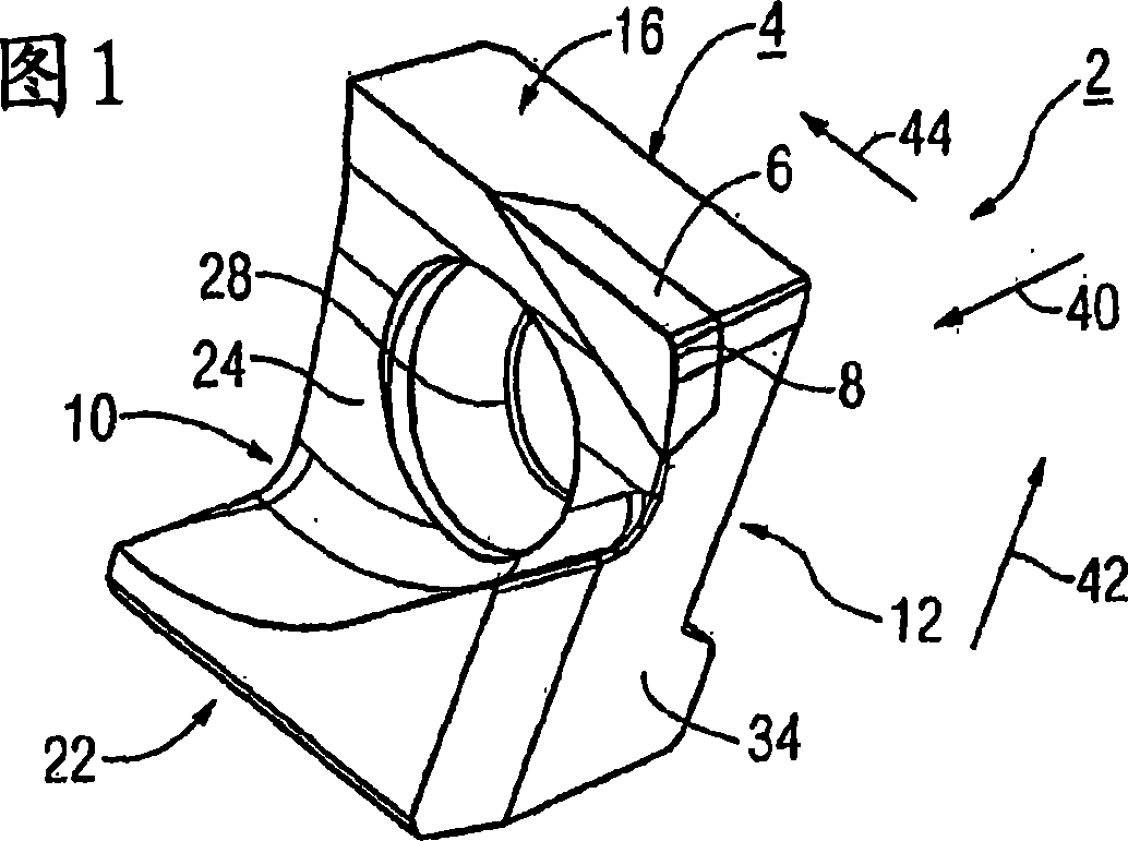
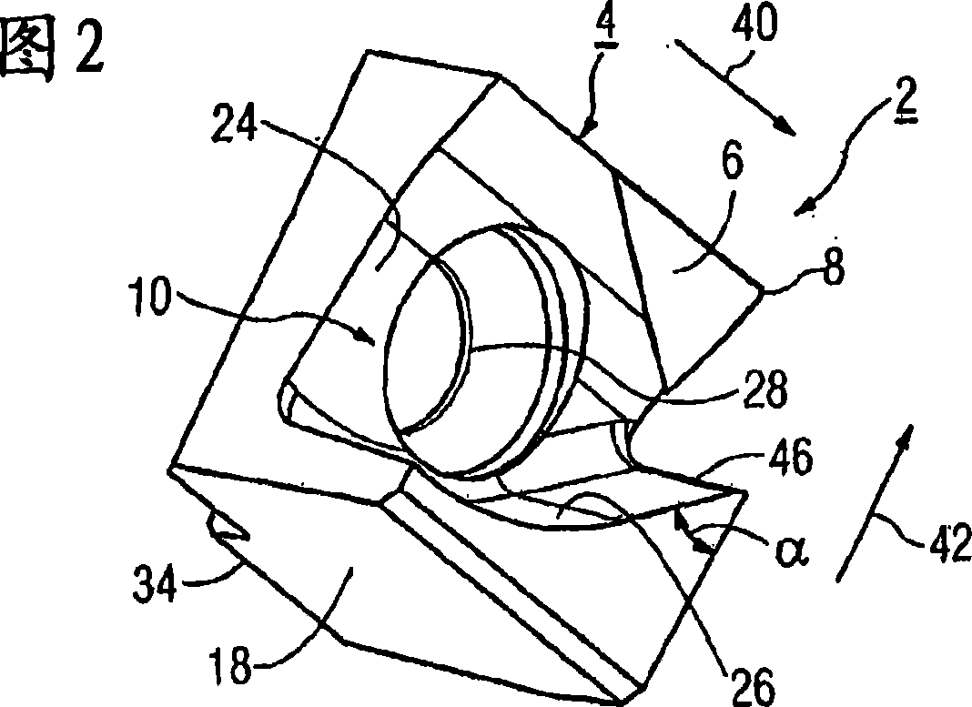
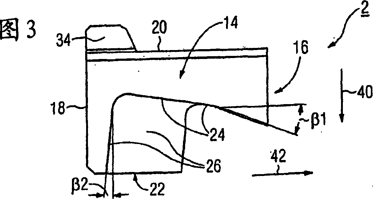
[0030] The cutting inserts described in FIGS. 1 to 5 are formed by a one-piece cutting body 2 which in turn consists of a sintered base body 4 and a cutting element 6 fastened thereto, in particular by brazing. The cutting element 6 is in particular a prism-shaped insert, as can be seen from FIGS. 1 and 2 . The cutting element 6 consists in particular of a polycrystalline diamond material. The base body 4 is produced by a sintering process of metal powder. In particular, complex geometries according to the present exemplary embodiment can be produced economically and with relatively little effort by means of the shaping and production method of the base body 4 .

[0031] The cutting insert 6 has a cutting edge 8 which is formed in particular as a cutting corner. During the machining of metal workpieces, the cutting edge 8 engages with the surface of the workpiece.

[0032]Ov...


PUM


Abstract

The cutting insert (2) is provided for the high-speed milling of light metals in particular aluminium. According to the invention, a reliable and defined cutting removal and a defined cutting forming may be guaranteed, whereby the cutting insert comprises a cutting guide surface (26) which runs into a machining surface(36), arranged at an acute angle (a) to a cutting edge (8).

Description

technical field [0001] The invention relates to a cutting insert for a tool, in particular a milling cutter, comprising a cutting body comprising a workpiece side face and a front end face, which form a corner region in which Set a cutting edge for cutting the workpiece. In addition, the cutting body has a chip guide surface. Background technique [0002] Such cutting inserts are described, for example, in DE 197 16 818 C2 or DE 20 2004 007 811 U1. The known cutting inserts are used accordingly in face milling. In this face milling cutter a plurality of inserts are fastened distributed around the circumference on a cylindrical tool base body. The tool base body consists of a light metal, in particular aluminum or an aluminum alloy. Due to the relatively soft material, in the prior art a chip guide element or a chip deflector is provided which, when cutting the workpiece, keeps the cut chips away from the basic tool body so that it cannot be damaged. In DE 197 16 818 C2 ...

Claims


Application Information

Patent Timeline
IPC IPC(8): B23C5/06B23C5/20B23C5/00B23B27/22B23C5/16B23C5/18
CPCB23C5/2204B23C2226/315B23C2226/125B23C5/165B23C2222/52B23C5/202B23C2222/04B23C5/06B23C2222/64
Inventor D·卡默迈尔N·K·R·米拉瓦拉姆M·贝尔纳德B·利布尔
Owner KENNAMETAL INC
Features
  • Generate Ideas
  • Intellectual Property
  • Life Sciences
  • Materials
  • Tech Scout
  • Unparalleled Data Quality
  • Higher Quality Content
  • 60% Fewer Hallucinations
Learn More