Concave-convex rotary engine

A rotary engine and concave cam technology, applied in the field of fuel engines, can solve the problems of large space and large shape of fuel engines

Inactive Publication Date: 2007-09-12
方洪伟
View PDF0 Cites 6 Cited by
  • Summary
  • Abstract
  • Description
  • Claims
  • Application Information

AI Technical Summary

Problems solved by technology

[0003] The object of the present invention is to provide a concave-cam rotary engine to overcome the defects that the fuel engine of the existing crank-piston mechanism has a relatively large overall shape and takes up a lot of space in the motor vehicle

Method used


Image

  • Concave-convex rotary engine
  • Concave-convex rotary engine
  • Concave-convex rotary engine

Examples


specific Embodiment approach 1

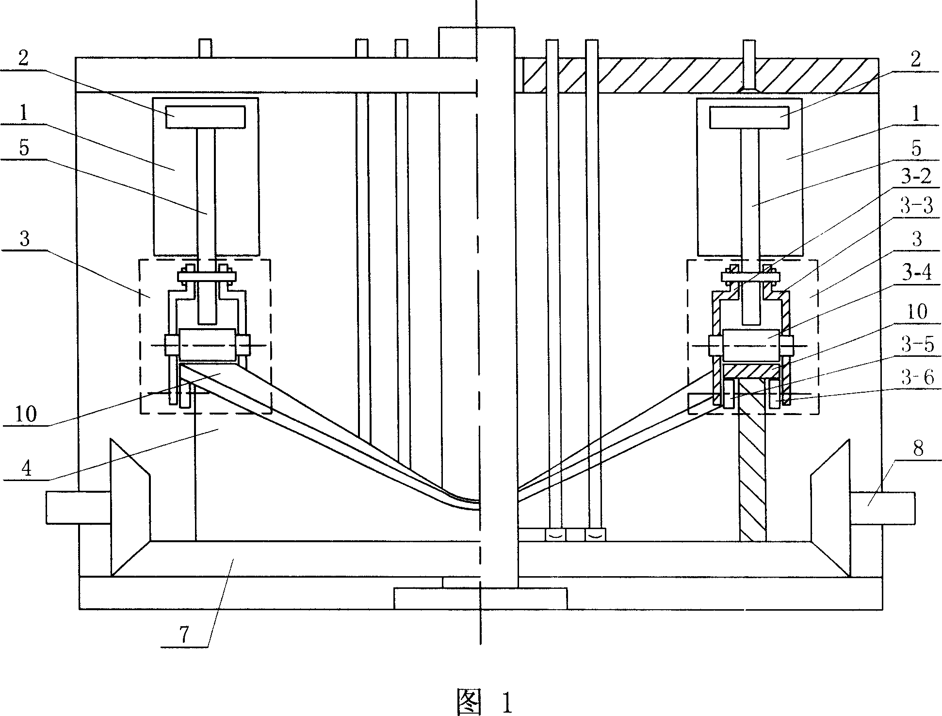
[0005] Specific Embodiment 1: The present embodiment will be specifically described below with reference to FIG. 1 . This embodiment is composed of two cylinders 1, two pistons 2, two dowel rods 5, two sets of connecting mechanisms 3, guide strips 10 and concave-convex wheel 4, the upper surface of the concave-convex wheel 4 has a height difference along its Guide bar 10 is fixed on the peripheral edge, cylinder 1 is arranged on the top of guide bar 10, two cylinders 1 are evenly distributed along the circumferential direction of guide bar 10, the upper end of dowel bar 5 is fixed on piston 2, and the dowel bar The lower end of 5 is connected with the guide bar 10 through the connecting mechanism 3 so as to realize the sliding of the lower end of the dowel 5 along the guide bar 10 . Connecting mechanism 3 is made up of left connecting splint 3-2, right connecting splint 3-3, upper wheel 3-4, left lower wheel 3-5 and right lower wheel 3-6, and left lower wheel 3-5 is arranged o...

specific Embodiment approach 2

[0006] Specific Embodiment 2: The present embodiment will be specifically described below with reference to FIG. 1 . The difference between this embodiment and Embodiment 1 is that it also includes a large bevel gear 7 and a small bevel gear 8, the large bevel gear 7 is fixed on the lower end surface of the concave-convex wheel 4 and is coaxial with it, the small bevel gear 8 and the large bevel gear The bevel gears 7 are meshed. In this embodiment, the rotary motion of the concave cam wheel 4 is output through the small bevel gear 8, and the large bevel gear 7 is used as the driving wheel to drive the small bevel gear 8, which improves the output speed. Therefore, under the same fuel consumption, the speed ratio The existing crankshaft internal combustion engine is more than doubled, reflecting good power and fuel economy.

specific Embodiment approach 3

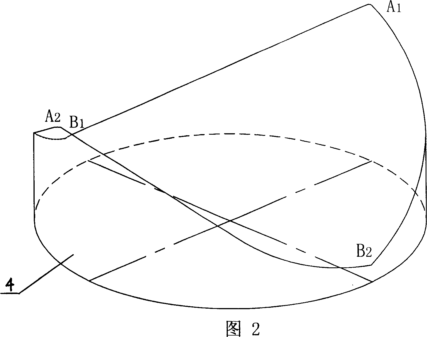
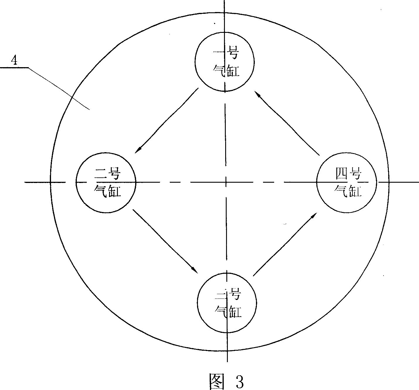
[0007] Specific Embodiment Three: The present embodiment will be specifically described below with reference to FIG. 2 and FIG. 3 . The difference between this embodiment and Embodiment 1 is that the upper end surface of the concave-convex wheel 4 is provided with a first raised high point A1, a first depressed low point B1, a second raised high point A2 and a second depressed low point B2 , the first convex high point A1, the first concave low point B1, the second convex high point A2 and the second concave low point B2 are uniformly arranged on the circumferential edge of the concave cam wheel 4 in sequence along the circumferential direction of the concave cam wheel 4, Cylinder 1, piston 2, dowel 5 and connecting mechanism 3 are respectively provided with four groups. Because there are two high points and two low points, this embodiment can implement a system cycle of continuous operation with continuous ignition. The ignition sequence is cycled in the working order of No....


PUM


Abstract

A well base rotary engine relates to a fuel-oil engine. It overcomes the defects of large configuration and much occupation space in automobile of the existed fuel-oil engine with crank plunger mechanism. It contains at least two cylinders (1), two plungers (2), two dowel steels (5), two groups of linking mechanisms (3), lead strip (10) and well base (4). The (10) is fixed on the upper surface with high-low fall of (4) around its circle brim. The (1) are set above (10) and are located uniformly along its direction. The upper end of (5) is fixed on (2) and its lower end links (10) through (3) to realize its sliding along (10). The (2) makes downward movement under gas expansive action. The (10) rotates winding self axel on horizontal direction when (5) compressing its high spot downward. As (1) in this invention arranges around circle of (4) replacing linear distribution of traditional cylinder, the distribution is dense and the structure is compact.

Description

technical field [0001] The invention relates to a fuel engine. Background technique [0002] The fuel engine used in traditional motor vehicles is basically a crank-piston mechanism, which uses the expansion force generated by the combustion of mixed oil and gas in the cylinder to do work and push the piston to move. The movement of the piston is output through the connecting rod and the crankshaft. Because existing engine basically adopts multi-cylinder structure, a plurality of cylinders share the structure of a crankshaft so that all cylinders can only be distributed along the linear direction of the crankshaft, causing the overall shape of the engine to be larger and occupying more space in the motor vehicle. Contents of the invention [0003] The object of the present invention is to provide a concave-cam rotary engine to overcome the defects that the fuel engine of the existing crank-piston mechanism has a relatively large overall shape and takes up a lot of space in...

Claims


Application Information

Patent Timeline
Patent Type & Authority Applications(China)
IPC IPC(8): F02B75/22F02B75/40F01B9/06
Inventor 方洪伟方洪渊
Owner 方洪伟
Why Eureka
Try Eureka