Network structure for realizing the full-optical virtual private network between more than two passive optical networks

A passive optical network and virtual private network technology, applied in the field of optical fiber communication, can solve problems such as flexibility limitations and achieve the effect of large access range

Inactive Publication Date: 2007-09-12
SHANGHAI JIAO TONG UNIV
View PDF0 Cites 21 Cited by
  • Summary
  • Abstract
  • Description
  • Claims
  • Application Information

AI Technical Summary

Problems solved by technology

This technology can also only realize the all-optical virtual private network in the same passive optical network, and the modulation pattern of the

Method used


Image

  • Network structure for realizing the full-optical virtual private network between more than two passive optical networks
  • Network structure for realizing the full-optical virtual private network between more than two passive optical networks
  • Network structure for realizing the full-optical virtual private network between more than two passive optical networks

Examples


Example Embodiment

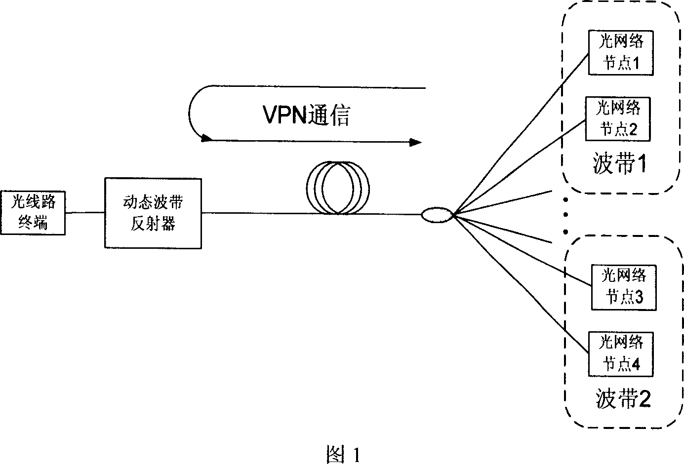
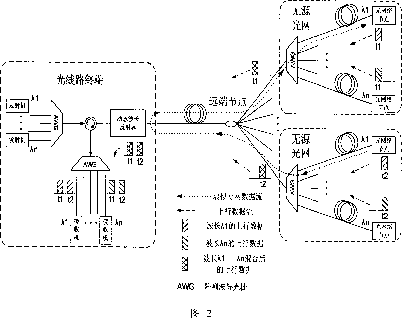
[0025] As shown in Figure 1, the optical network nodes in the same passive optical network use different wavelengths (λ1, λn) (n is the number of wavelengths used in the network) to transmit uplink data, which is coupled into one through the arrayed waveguide grating optical fiber. Different passive optical networks use different time slots for communication (t1, t2), coupled together through the 1:N coupler of the remote node, and transmitted to the optical line terminal. If the dynamic reflector pairs λ1 and λn (n is the number of wavelengths used in the network) are in the pass state, the optical signal passes through the reflector, passes through the circulator and the arrayed waveguide grating, and is received by the corresponding receiver. If the dynamic reflector is reflecting a certain wavelength (λ1), its uplink signal will be reflected back to the remote node, and then broadcast to all passive optical networks, and be received by the optical network node of the correspon...


PUM


Abstract

A fiber optic communication technology relates to more than two passive optical networks to achieve all-optical VPN network structure. It includes the following steps: a more than two transmitters and receivers, and more than one road reflector dynamic wavelength composed of optical line terminal, using a fiber, and a number of transmitters than the opt coupler with a remote nodes connected, remote nodes connected to the output corresponding Passive Optical Network, a network of first-class;Passive Optical Network, the feeder lines from remote nodes through a arrayed waveguide grating (AWG) and the number of optical network unit attached to a second-class network . This inventioncombines TDM and WDM network structure of the levels,connects more usersand cover greater access in the wider regionvirtual private network connectivity.

Description

technical field [0001] The invention relates to a method in the technical field of optical fiber communication, in particular to a network structure for realizing an all-optical virtual private network between two or more passive optical networks. Background technique [0002] Utilizing the existing low-cost optical devices, the passive optical network (PON) has become an attractive solution for users to realize broadband access because of its simple structure and low cost. Traditionally, it adopts a tree topology, where the optical line terminal (OLT) or central office delivers services to remote nodes (RN) through a long optical fiber, where the optical power is split and further transmitted to many optical network units (ONUs). ). Each optical network unit can provide services for multiple users. In order to further improve the flexibility and reliability of the network, it is necessary to support the internal communication of the optical network unit and establish an a...

Claims


Application Information

Patent Timeline
IPC IPC(8): H04B10/12H04L12/46H04B10/25
Inventor 田玥苏翼凯叶通
Owner SHANGHAI JIAO TONG UNIV
Why Eureka
Try Eureka