
Combined electrostatic dust separator

A technology of electrostatic precipitator and electric field, which is applied in the field of composite electrostatic precipitator to achieve the effects of saving energy consumption, improving removal efficiency, and improving dust removal efficiency

Active Publication Date: 2007-10-03
ZHEJIANG UNIV
View PDF0 Cites 15 Cited by
  • Summary
  • Abstract
  • Description
  • Claims
  • Application Information

AI Technical Summary

Problems solved by technology

Respirable particulate matter entering the atmosphere can cause many environmental and health problems

Method used


Image

  • Combined electrostatic dust separator
  • Combined electrostatic dust separator
  • Combined electrostatic dust separator

Examples


Embodiment Construction

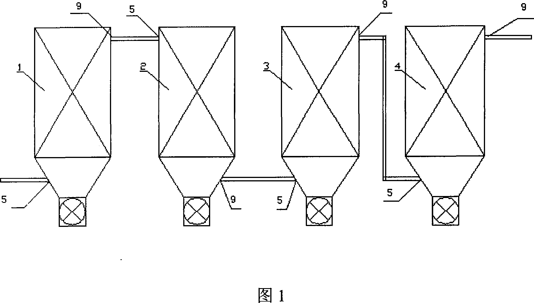
[0018] As shown in Figure 1, the composite electrostatic precipitator is characterized in that it has a first-stage DC discharge electric field 1, a second-stage pulse discharge electric field 2, a third-stage DC discharge electric field 3, and a fourth-stage DC discharge electric field 4. The electric field and the pulse discharge electric field have a dust collection area in the discharge area, the first-level DC discharge electric field 1, the third-level DC discharge electric field 3, and the fourth-level DC discharge electric field 4. The dust collection area is equipped with a flue gas inlet 5, and the first-level DC discharge Electric field 1, the third-level DC discharge electric field 3, the fourth-level DC discharge electric field 4, the upper end of the discharge area is provided with a flue gas outlet 9, the upper end of the second-level pulse discharge electric field 2 is provided with a flue gas inlet 5, and the second-level pulse discharge The dust collection are...


PUM


Abstract

A combined electrostatic dust separator for removing the nanoparticles is composed of the first high-voltage DC discharging electric field connected to harmful fume pipeline for pre-collecting dust, the second high-voltage pulse discharging electric field for electrically charging the dust particles, and the third and fourth high-voltage DC discharging electric fields for coagulating and collecting dust.

Description

technical field [0001] The invention relates to a dust collector, in particular to a compound electrostatic dust collector. Background technique [0002] Coal is the main source of electricity in our country. In the foreseeable next few decades, coal-fired thermal power generation will occupy a dominant position in my country's power industry for a long time. This long-term energy structure that relies on coal-fired power generation has caused serious environmental pollution. The smoke and dust emitted by coal-fired power plants is one of the important sources of inhalable particulate matter in the atmosphere. Inhalable particulate matter, especially particulate matter (PM2.5) with a diameter of less than 2.5 microns is an important pollutant affecting the air quality of our country. The harm is huge and has attracted widespread attention from the international community. [0003] At present, most power plants in my country use electrostatic precipitators (ESP) to collect ...

Claims


Application Information

Patent Timeline
Patent Type & Authority Applications(China)
IPC IPC(8): B03C3/00B03C3/04B03C3/86B03C3/40B03C3/66
Inventor 骆仲泱高翔岑可法方梦祥施正伦周劲松程乐鸣王勤辉王树荣余春江倪明江
Owner ZHEJIANG UNIV
Learn More