Apparatus for laser cutting and/or marking

A marking and laser beam technology, applied in laser welding equipment, large fixed members, program control manipulator, etc., can solve the problem of high motor cost, achieve low cost, ensure productivity, and simple maintenance

Inactive Publication Date: 2007-10-03
赛股份有限公司
View PDF3 Cites 4 Cited by
  • Summary
  • Abstract
  • Description
  • Claims
  • Application Information

AI Technical Summary

Problems solved by technology

But this type of motor is expensive

Method used


Image

  • Apparatus for laser cutting and/or marking
  • Apparatus for laser cutting and/or marking

Examples


Embodiment Construction

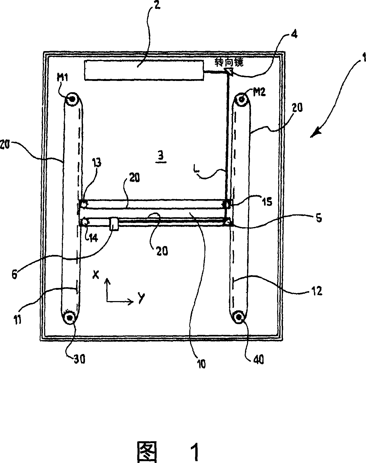
[0045] Figure 1 is a diagram of a device 1 according to the invention. The device comprises a laser source 2 arranged at a fixed position, which generates a laser beam L suitable for cutting and marking the product to be processed. For example a laser source may have a power of about 500W. The laser beam L generated by the laser source 2 is directed towards the working plane 3 by means of a series of focusing and reflecting optics 4, 5, 6 such as prisms, lenses, mirrors, focusing heads etc.

[0046] A product with a substantially planar structure is positioned on the working plane 3 for cutting or marking by the laser beam L. In the illustrated embodiment, the working plane 3 has a 1000×700mm 2 size, but in general its size can be different, for example 300×300mm 2 or 1000×1000mm 2 and bigger.

[0047] The focusing head 6 receives the laser beam L transferred by the mirrors 4 and 5 and focuses it on the product positioned on the working plane 3 . The focusing head 6 may ...


PUM


Abstract

The present invention relates to an apparatus for cutting and/or marking products by means of laser beams. The apparatus comprises at least one laser light emitter moveable in a first direction (X) along a cross-bar, the cross-bar being in turn moveable above a working plan in a second direction transversal to said first direction (X), and at least two motors for moving the laser light emitter and the cross-bar. The laser light source is positioned to direct a laser light beam onto said working plan. Advantageously the two motors are positioned fixed and are coupled together and both to the laser light source, and to the cross-bar, by means of a transmission belt.

Description

technical field [0001] The invention relates to a device for laser cutting and / or marking, in particular to a device for cutting and / or marking foil or foil products by means of a laser. Background technique [0002] Devices have been available on the market for a long time which allow cutting, or marking, of different materials by means of a laser beam. Such laser devices can be used, for example, for cutting and marking semi-finished and finished products made of methacrylate, plastic, acetate, polyester, wood, paper, leather, metal, as well as organic or synthetic products. [0003] Through-cutting is achieved by striking the material with a high-intensity laser beam capable of passing through the entire thickness of the material. Marking and embossing (surface cutting) are achieved by impinging the material with a laser beam of lower intensity so that only the surface of the material is modified, thereby defining patterns, pictures, logos, writing, etc. [0004] Laser ...

Claims


Application Information

Patent Timeline
Patent Type & Authority Applications(China)
IPC IPC(8): B23K26/08B41M5/24
CPCB25J9/026B23K26/38Y10T74/18848B23Q1/621B23K26/10B25J9/104
Inventor E·富斯蒂诺尼
Owner 赛股份有限公司
Why Eureka
Try Eureka