

Laser oscillator
A laser oscillator and laser technology, applied in the direction of lasers, laser components, phonon exciters, etc., can solve the problems of reduced cooling performance, poor heat transfer performance, and poor flatness of reflecting surfaces, etc., to achieve the goal of improving cooling performance Effect
- Summary
- Abstract
- Description
- Claims
- Application Information
AI Technical Summary
Problems solved by technology
Method used
Image

Examples
Embodiment approach 1
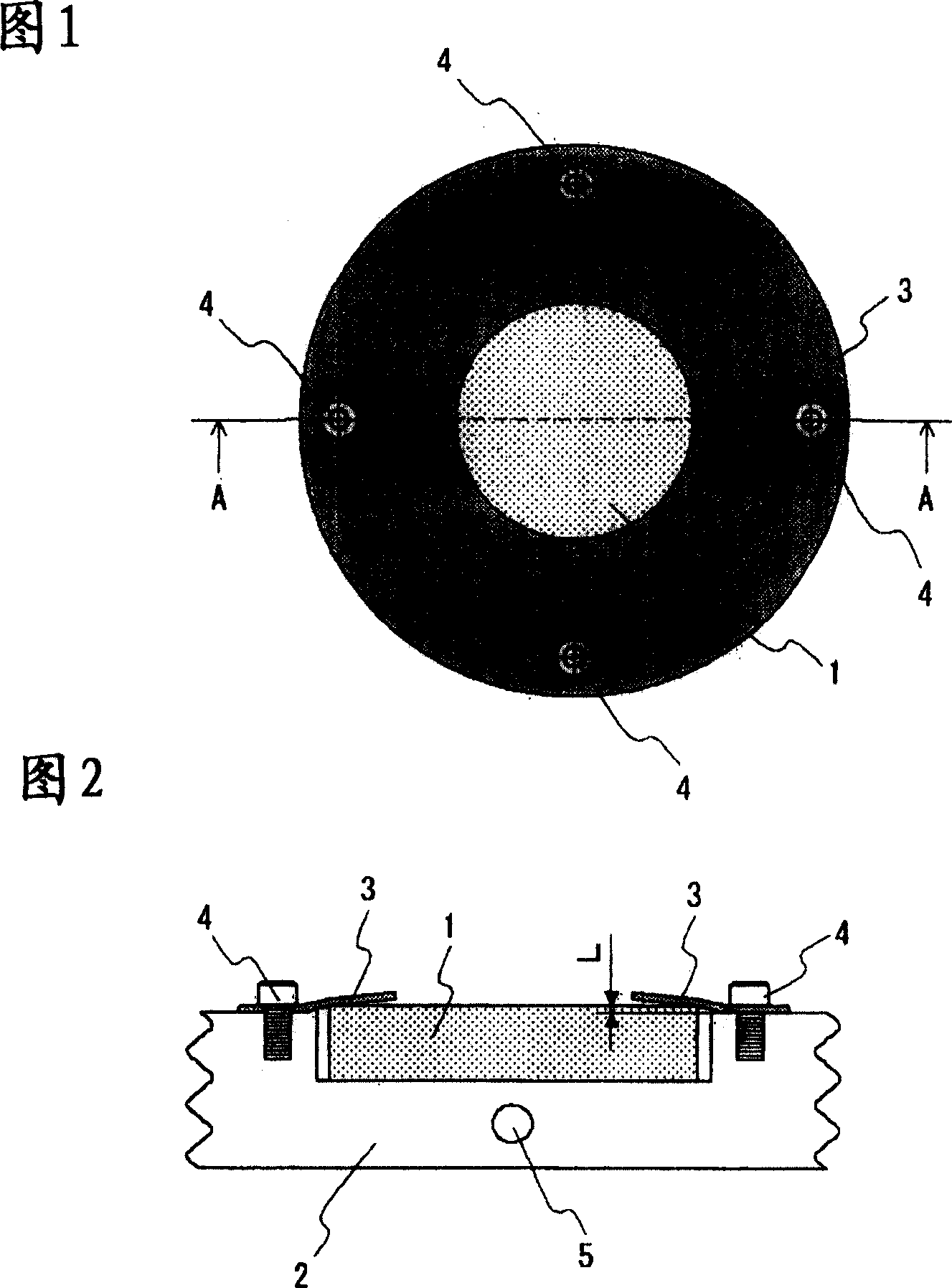
[0021] FIG. 1 is a structural diagram of a mirror mounting portion of a laser oscillator according to Embodiment 1 of the present invention. Fig. 2 is an A-A sectional view of the mirror mounting portion shown in Fig. 1 . The holder 2 is not shown in FIG. 1 . In Fig. 1 and Fig. 2, the mirror 1 is circular and reflects the laser light oscillating inside the laser oscillator. By adjusting the orientation of the reflection surface of the mirror 1, the optical axis of the laser can be adjusted. The mirror 1 is inserted into and held in a concave portion of a holder 2 serving as a mirror holding portion. Of the two planes of the reflecting mirror 1 , the surface on which the laser light is reflected is the reflecting surface (the surface in contact with the plate spring 3 ). The thickness of the reflector 1 is greater than the depth of the concave portion of the holder 2 , so that a step is formed between the reflective surface of the reflector 1 and the mounting surface of the ...
Embodiment approach 2
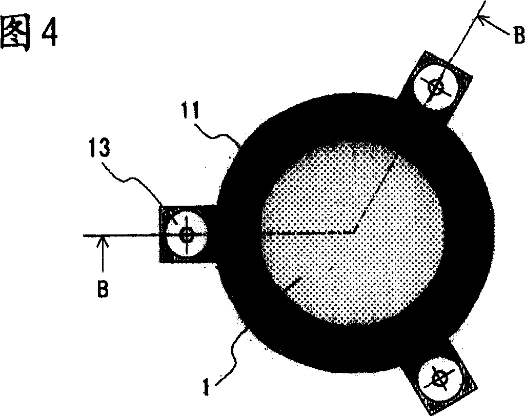
[0044] 4 is a structural diagram of a mirror mounting portion of a laser oscillator according to Embodiment 2 of the present invention. Fig. 5 is a B-B sectional view of the mirror mounting portion shown in Fig. 4 . The holder 2 is not shown in FIG. 4 . The difference between FIGS. 4 and 5 and Embodiment 1 is that the mirror mounting part presses the mirror 1 against the holder 2 by the coil spring 12 through the mirror pressing plate 11 . In Fig. 4 and Fig. 5, the same symbols as those in Fig. 1 and Fig. 2 represent the same or corresponding parts, which are common throughout the specification. In addition, the forms of the constituent elements described in the specification are only For example, the present invention is not limited to these descriptions.
[0045] The reflector 1 is mounted on the holder 2 by the urging force of the coil spring 12 through the reflector pressure plate 11 . That is, the coil spring 12 pushes the mirror 1 through the mirror pressing plate 11 ...
Embodiment approach 3
[0051] 6 is a structural diagram of a mirror mounting portion of a laser oscillator according to Embodiment 3 of the present invention. Fig. 7 is a C-C sectional view of the mirror mounting portion shown in Fig. 6 . The holder 14 is not shown in FIG. 6 . 6 and 7 are different from Embodiment 2 in that protrusions are provided on the holder 14 and the mirror holding plate 15 .
[0052] The reflector 1 is mounted on the holding seat 14 by the urging force of the coil spring 16 through the reflector pressing plate 15 , and the reflecting mirror pressing plate 15 is provided with a protrusion 15 a protruding toward the reflecting mirror 1 side. The coil spring 16 is an elastic member that presses and fixes the reflector 1 to the holder 14 from the reflective surface side. The mirror holding plate 15 is composed of an annular portion that presses the mirror 1 , and portions protruding radially outward at three locations fixed to the holder 14 by coil springs 16 and screws 17 . T...
PUM
| Property | Measurement | Unit |
|---|---|---|
| Flatness | aaaaa | aaaaa |
Abstract
Description
Claims
Application Information