Airleg rock drill

A rock drill and air leg technology, which is applied in the field of air leg rock drills, can solve the problems of reduced impact energy, short piston stroke, and poor exhaust in the front chamber.

Inactive Publication Date: 2007-10-10
王光临
View PDF0 Cites 5 Cited by
  • Summary
  • Abstract
  • Description
  • Claims
  • Application Information

AI Technical Summary

Problems solved by technology

[0006] The technical problem of the traditional air leg rock drill: when the piston returns over the exhaust groove, the gas in the rear chamber of the cylinder starts to compress. During the stroke of the piston, due to the poor exhaust of the front cavity, the air cushion is formed prematurely, resulting in the short stroke of the piston during the reciprocating motion, the impact energy is reduced, and the efficiency is low

Method used


Image

  • Airleg rock drill
  • Airleg rock drill
  • Airleg rock drill

Examples


Embodiment Construction

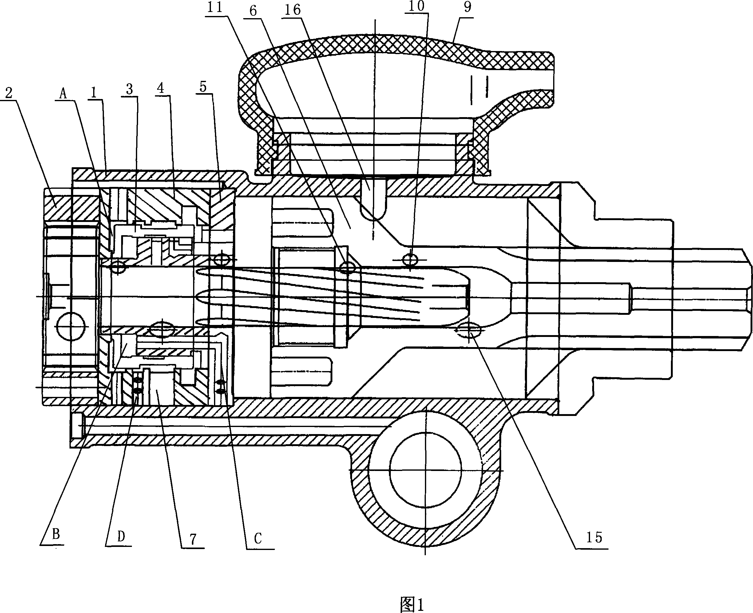
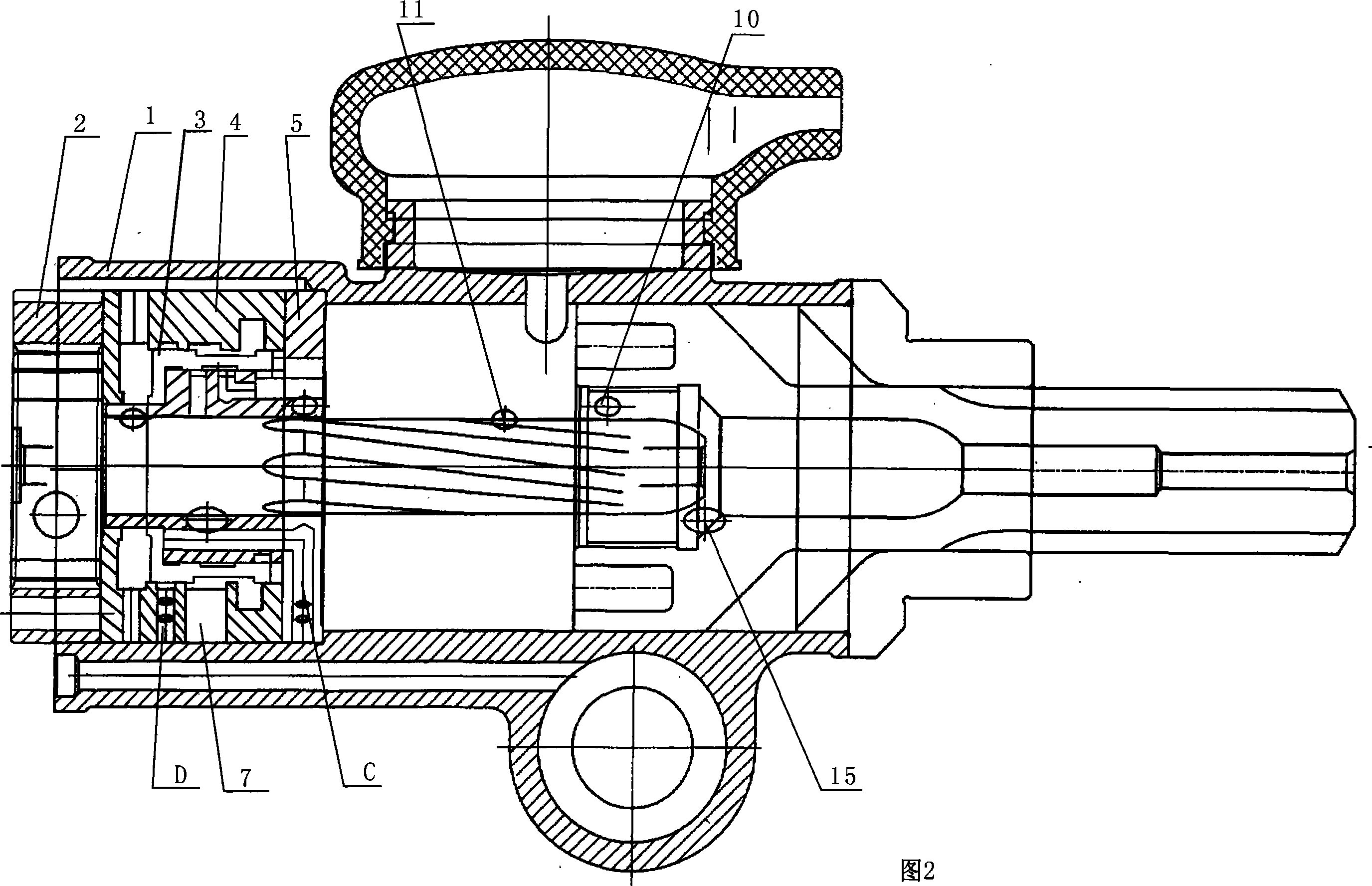
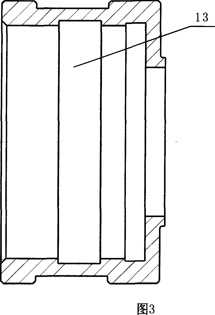
[0026] As shown in Figures 1, 2, 3, 4, 5, and 6: the air leg rock drill includes three parts: a handle body, a cylinder body (1) and a machine head; the cylinder body (1) has a built-in valve body, and the valve body The body consists of a valve cover (5), a reversing valve (3) that can slide left and right on its shaft, and a valve cabinet (4); the D section of the valve cabinet (4) has four vent holes (8a). , newly dug with annular groove (13) on the inner circle of its reversing valve (3). The four newly dug radial holes (14a) in the first annular groove (17) communicate with the newly dug four axial holes (12) on the valve cover (5). The four newly dug radial holes (14b) in the second annular groove (18) communicate with the newly dug four radial exhaust holes (8b) on the side of the valve cover (5). There are 4 axial holes (12) newly excavated on the right end face of its bonnet (5), and 4 exhaust holes (8b) are newly excavated on the side of the bonnet (5); Two annular...


PUM


Abstract

The present invention relates to an air-feed leg rock drill, belonging to the field of pneumatic machinery technology. It includes three portions of cylinder body, holder body and machine head. In the cylinder body interior a valve body is set, said valve body is formed from valve cover, reversal valve which can be leftwards and rightwards slided on its shaft and valve chest. On D section of its valve chest four exhaust outlets are cut, on the internal circumferential surface of its reversal valve a circular groove is cut, on the right end face of its valve cover several axial holes are set, four radial holes cut in first circular groove are communicated with four axial holes cut on the valve cover and four radial holes cut in second circular groove are communicated with four axial holes set on the side surface of valve cover. Said invention can increase stroke of piston and can raise impact energy.

Description

technical field [0001] The invention relates to the technical field of pneumatic machinery, and relates to an air-leg rock drill widely used in rock blast hole operations in mines, transportation, national defense, water conservancy and hydropower projects. Background technique [0002] At present, the working principle of the traditional air-leg rock drill is that when the high-pressure gas is introduced into the gas distribution mechanism through the handle body, a movable reversing valve alternately guides the compressed gas into the front chamber and the rear chamber of the cylinder body, and pushes the piston to reciprocate at high speed. sports. During the stroke, the piston impacts the drilling tool to break rocks; during the return stroke, the piston drives the drilling tool to rotate at a certain angle, and the continuous impact and rotation make the drilling tool chisel out a circular blast hole on the rock or other working objects. [0003] The working process of...

Claims


Application Information

Patent Timeline
Patent Type & Authority Applications(China)
IPC IPC(8): E21B1/30
Inventor 王光临
Owner 王光临
Why Eureka
Try Eureka