Circulation air path of air cooling type refrigerator

A circulating air duct and air-cooled technology, which is applied in the field of refrigeration equipment, can solve problems such as increased energy consumption, reduced refrigerator efficiency, and particularly obvious pressure loss, and achieves the effects of reducing dead angle, improving refrigeration effect, and improving heat exchange efficiency

Active Publication Date: 2007-10-10
HAIER GRP CORP +1
View PDF1 Cites 22 Cited by
  • Summary
  • Abstract
  • Description
  • Claims
  • Application Information

AI Technical Summary

Problems solved by technology

Although the temperature in the compartment can be controlled within a certain range by using the damper to control the air supply volume of each compartment, the pressure loss caused by the adjustment of the damper is also inevitable. However, in the current air-cooled refrigerator, the damper is set at the evaporation On the air supply ducts of the refrigerator and each temperature zone, the wind pressure and wind speed on the air supply ducts are relatively high, which makes the pressure loss caused by the adjustment of the damper particularly obvious, resulting in a decrease in the efficiency of the refrigerator and an increase in energy consumption.

Method used


Image

  • Circulation air path of air cooling type refrigerator
  • Circulation air path of air cooling type refrigerator
  • Circulation air path of air cooling type refrigerator

Examples


Embodiment 1

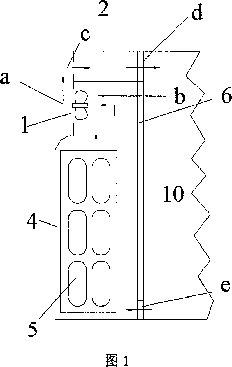
[0028] See Figure 1, where 1 is the axial flow fan, 2 is the air outlet, d is the air outlet, e is the return air outlet, 4 is the cooling chamber, 5 is the evaporator, 6 is the rear side panel of the storage room, and 10 is the storage room. Between objects, the cooling chamber 4 is separated from the storage room 10 by the rear side plate 6 between the storage rooms.

[0029] Wherein, the airflow generated when the axial flow fan 1 rotates flows in the direction of the arrow c, positive pressure is formed in area a, and negative pressure is formed in area b; the rear side panel 6 of the storage room is provided with an air outlet d and a return air outlet e;

[0030] When the axial flow fan 1 is running, a positive pressure is formed in area a, and a negative pressure is formed in area b, thereby generating air flow; the air flow in area a flows to the air outlet d in the direction indicated by arrow c, and then enters the storage room. Heat exchange with refrigerated or fro...

Embodiment 2

[0032] This embodiment is the result of optimizing it on the basis of Embodiment 1.

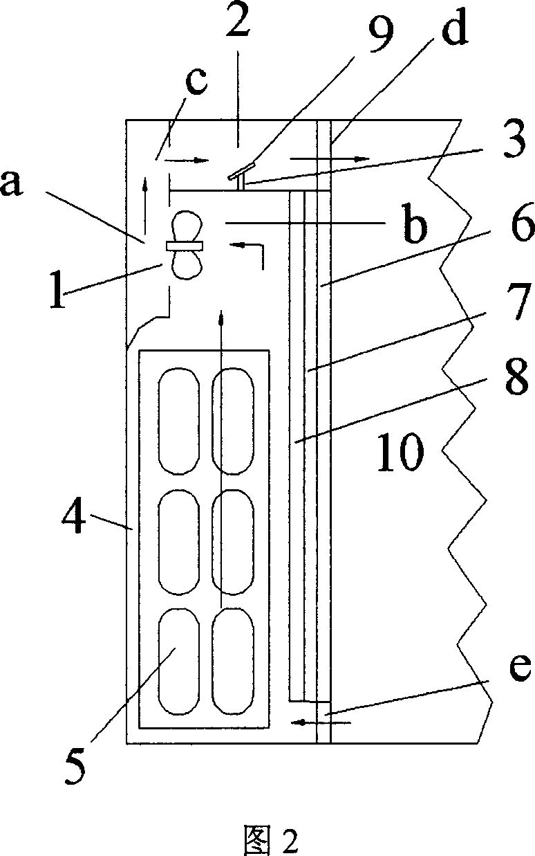
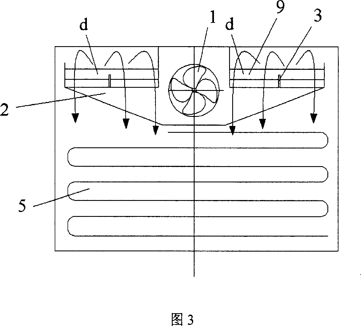
[0033] See Figure 2, where 1 is the axial fan, 2 is the air outlet, 3 is the rib, d is the air outlet, e is the return air outlet, 4 is the cooling room, 5 is the evaporator, and 6 is the rear side of the storage room Plate, 9 is a deflector, 10 is a storage room, and the cooling chamber 4 and the storage room 10 are separated by the rear side plate 6 of the storage room.

[0034] Wherein, the airflow generated when the axial flow fan 1 rotates flows in the direction of the arrow c, positive pressure is formed in area a, and negative pressure is formed in area b; the rear side panel 6 of the storage room is provided with an air outlet d and a return air outlet e;

[0035] Wherein, the insulation layer 7 is a foamed plastic board, and the effect of setting the plastic board is to reduce the heat loss caused by the heat exchange between the cooling chamber 4 and the storage room, avoid unnecess...

Embodiment 3

[0041] This embodiment is the result of adjusting the horizontal inclination angle of the deflector 9 on the basis of the second embodiment, and the rest of the features remain unchanged.

[0042] The horizontal layer of the deflector fixed in the air duct is a sheet structure inclined upward by 30° along the air supply duct opening d.


PUM


Abstract

A circulation air dust of refrigerator in air cooling type is prepared for connecting cooling chamber set between refrigerator back wall and storeroom to air inlet of fan, connecting air outlet of fan to air outlets through air outlet dust, setting air outlets at two sides of back side plate on storeroom of refrigerator, setting a return air port at each of two bottom sides on back side plate of storeroom and locating two return air port at bottom of cooling chamber on evaporator.

Description

technical field [0001] The invention relates to a circulating air duct of an air-cooled refrigerator, belonging to the technical field of freezing devices. Background technique [0002] Refrigerators can be divided into direct cooling and air cooling. Air-cooling refrigerators are designed with a cooling room inside the refrigerator. The cooling room is generally between the food storage area of ​​the refrigerator and the back of the cabinet. The cooling room is equipped with main refrigeration components. One of the evaporators and the forced convection fan communicate with the cooling chamber and the food storage area with an air duct. The forced convection fan in the cooling room is near the evaporator. Under the action of the fan, the airflow is forced to flow through the surface of the evaporator and blow cold air to the storage area. The cold air takes away the heat from the storage area and returns to the cooling room. This cycle repeats. Under the control of the ref...

Claims


Application Information

Patent Timeline
Patent Type & Authority Applications(China)
IPC IPC(8): F25D11/00F25D17/06
Inventor 王东宁高丽霞赵明华赵建忠
Owner HAIER GRP CORP
Why Eureka
Try Eureka