Plant and internal combustion engine control device

A control system and internal combustion engine technology, applied in general control systems, control/regulation systems, engine control, etc., can solve problems such as the control of the pressure in the intake pipe and the control of the amount of inhaled air

Inactive Publication Date: 2007-10-10
HONDA MOTOR CO LTD
View PDF2 Cites 1 Cited by
  • Summary
  • Abstract
  • Description
  • Claims
  • Application Information

AI Technical Summary

Problems solved by technology

As a result, in the above-mentioned control system, there is a problem that the control of the press

Method used


Image

  • Plant and internal combustion engine control device
  • Plant and internal combustion engine control device
  • Plant and internal combustion engine control device

Examples


Embodiment Construction

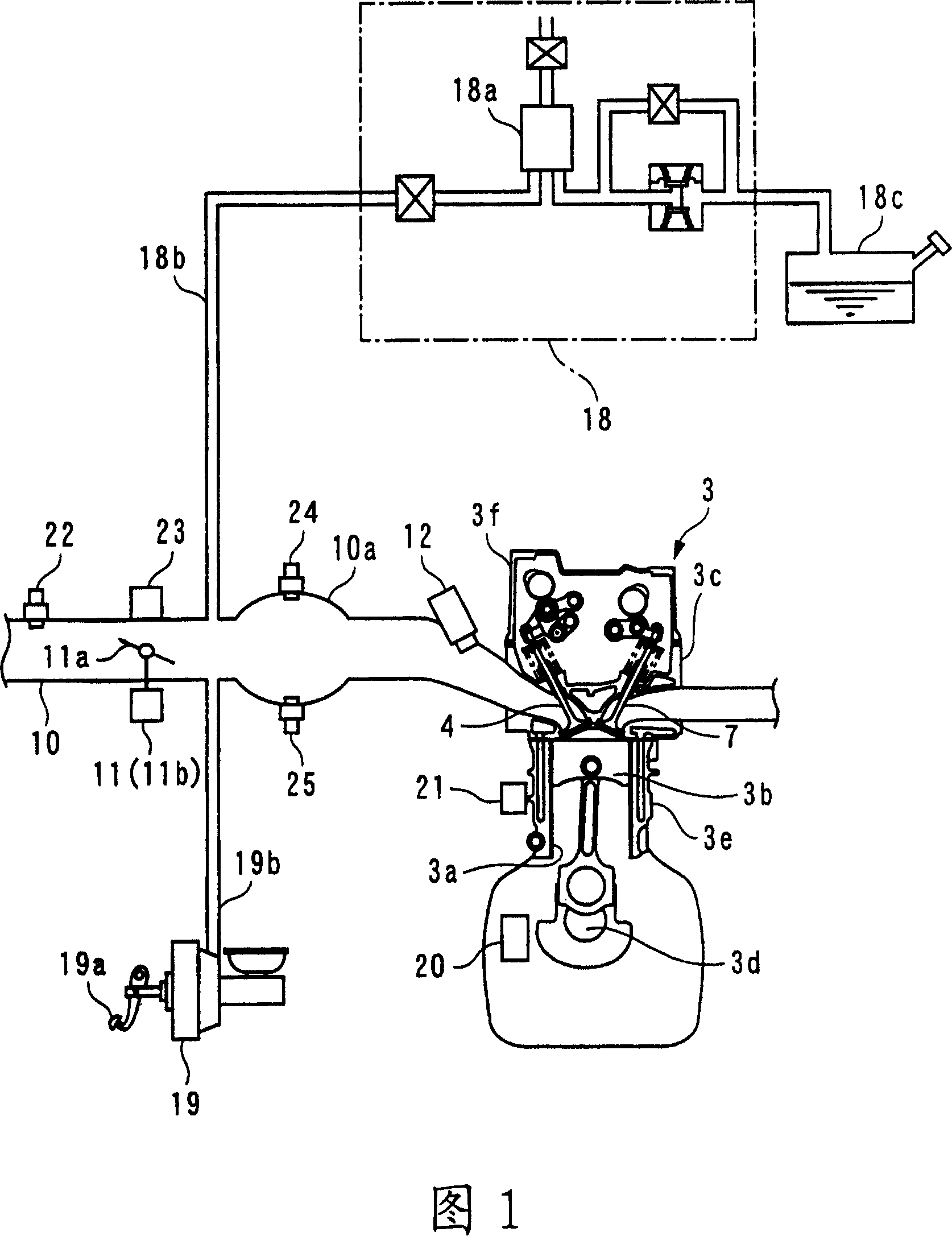
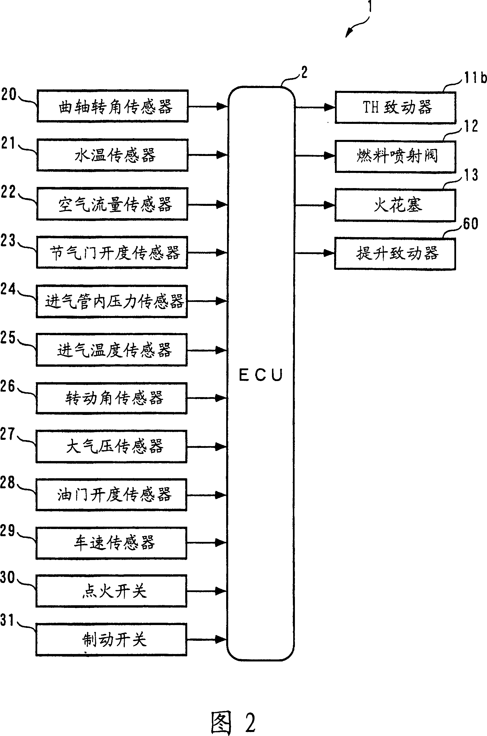
[0100] Hereinafter, a control system according to a first embodiment of the present invention will be described with reference to the drawings. As shown in FIG. 2 , the control system 1 includes an ECU 2 that executes control processing such as variable mechanism control processing in accordance with the operating state of an internal combustion engine (hereinafter referred to as "engine") 3 as will be described later.

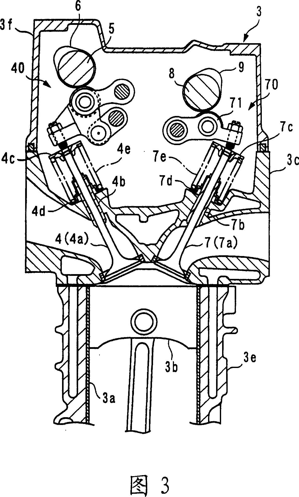
[0101]As shown in FIGS. 1 and 3 , the engine 3 is an inline four-cylinder gasoline engine having four sets of cylinders 3 a and pistons 3 b (only one set is shown), and is mounted on an unillustrated vehicle. The engine 3 has: an intake valve 4 and an exhaust valve 7 which are provided for each cylinder 3a to respectively open and close the intake port and the exhaust port; an intake camshaft 5 and an intake cam 6 for driving the intake valve 4; Variable intake valve transmission mechanism 40 for opening and closing driving intake valve 4; exhaust camshaft 8 a...


PUM


Abstract

There is provided a plant and internal combustion engine control device capable of improving controllability and control accuracy when controlling a plurality of control amounts while eliminating interference between control inputs and control amounts. A plant (90) has interference between TH_cmd, Liftin_cmd as control input and PB, Gcyl as control amounts. The control device (1) of the plant (90) uses a predetermined control algorithm which combines a predetermined response-specifying type control algorithm (expressions (2) to (8)) and a predetermined non-interference control algorithm expression (9) based on a plant model (expression (20)) in which the plant (90) is modeled as a discrete time system model. The two control inputs TH_cmd and Liftin_cmd are calculated as two non-interference inputs eliminating interference so that PB and Gcyl follow the target values PB_cmd and Gcyl_cmd.

Description

technical field [0001] The present invention relates to a control system of a device with mutual interference between a plurality of control inputs and a plurality of control quantities, and a control system of an internal combustion engine for respectively controlling a plurality of control quantities in an internal combustion engine according to a plurality of control inputs. Background technique [0002] Conventionally, a control system described in Patent Document 1 has been known as a control system for controlling a polishing robot. In this control system, a sliding mode non-disturbance control algorithm combining a sliding mode control algorithm and a non-disturbance control algorithm is used to control the polishing robot as follows. [0003] First of all, the grinding device including the grinding robot is regarded as such equipment: the driving force fmx and fmy of the x-direction and y-direction of the grinding robot are used as two control inputs, and the positio...

Claims


Application Information

Patent Timeline
IPC IPC(8): F02D45/00G05B11/32G05B13/00
CPCY02T10/144Y02T10/12
Inventor 安井裕司
Owner HONDA MOTOR CO LTD
Why Eureka
Try Eureka