Core mould vibrating bar for core mould vibrating machine

A vibrating machine and vibrating rod technology, applied in the direction of ceramic molding machines, manufacturing tools, etc., can solve the problems of deteriorating motor working conditions, high maintenance difficulty, and increased maintenance difficulty, so as to reduce the incidence of accidents and maintenance, and achieve good working conditions. The effect of reducing the number of motors

Inactive Publication Date: 2007-10-17
上海闵马水泥制管有限公司
View PDF0 Cites 2 Cited by
  • Summary
  • Abstract
  • Description
  • Claims
  • Application Information

AI Technical Summary

Problems solved by technology

[0004] 1. Since the mandrel is in the center of the product mold, when the motors are working at full load, the heat generated by the 18 motors cannot be fully dissipated, and the internal temperature is very high, resulting in deterioration of the working conditions of the motors and shortening their service life;
[0005] 2. Since the vibration source is synchronously driven by 18 motors through the coupling device, if one or several motors fail, it will cause the entire core mold vibrating machine to stop working, and the accident rate and maintenance rate are high;
[0006] 3. Every time a motor is damaged, it must be imported from abroad. There is no replaceable product in China. The cost of each motor is about 10,000 yuan. It costs about 500,000 yuan a year for this item alone, and the maintenance cost is high;
[0007] 4. Maintenance takes a long time and is difficult to maintain
Since the parts need to be imported from abroad, the waiting time for the parts is long, which affects the company's normal production arrangement, and the structure of the German mandrel is complicated and the disassembly procedures are cumbersome, which makes maintenance more difficult
And domestic similar products have not yet

Method used


Image

  • Core mould vibrating bar for core mould vibrating machine
  • Core mould vibrating bar for core mould vibrating machine
  • Core mould vibrating bar for core mould vibrating machine

Examples


Embodiment

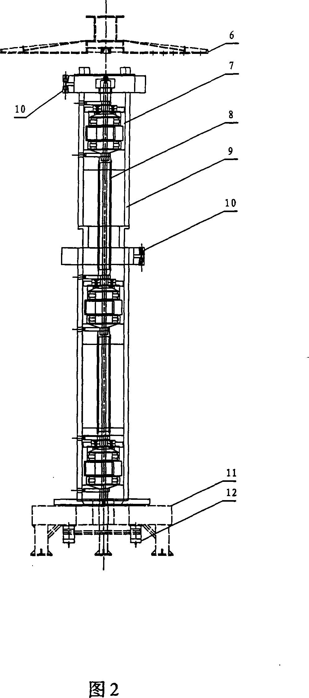
[0022] As shown in Figure 2, it is a schematic structural diagram of a core mold vibrating rod used for a core mold vibrating machine. The core mold vibrating rod used for a core mold vibrating machine is composed of an indenter cap 6, an eccentric block device 7, Central shaft 8, sleeve pipe 9, locking block 10, frame 11 and motor 12 are formed.

[0023] The three eccentric block devices 7 are connected and installed in the casing 9 through the central shaft 8, the two casings 9 are connected through the locking block 10, the pressure head cap 6 is set on the upper end of the casing 9, and the casing 9 is installed vertically on the frame 11, two motors 12 are installed at the bottom of the frame 11, and the motors 12 are connected with the central shaft 8.

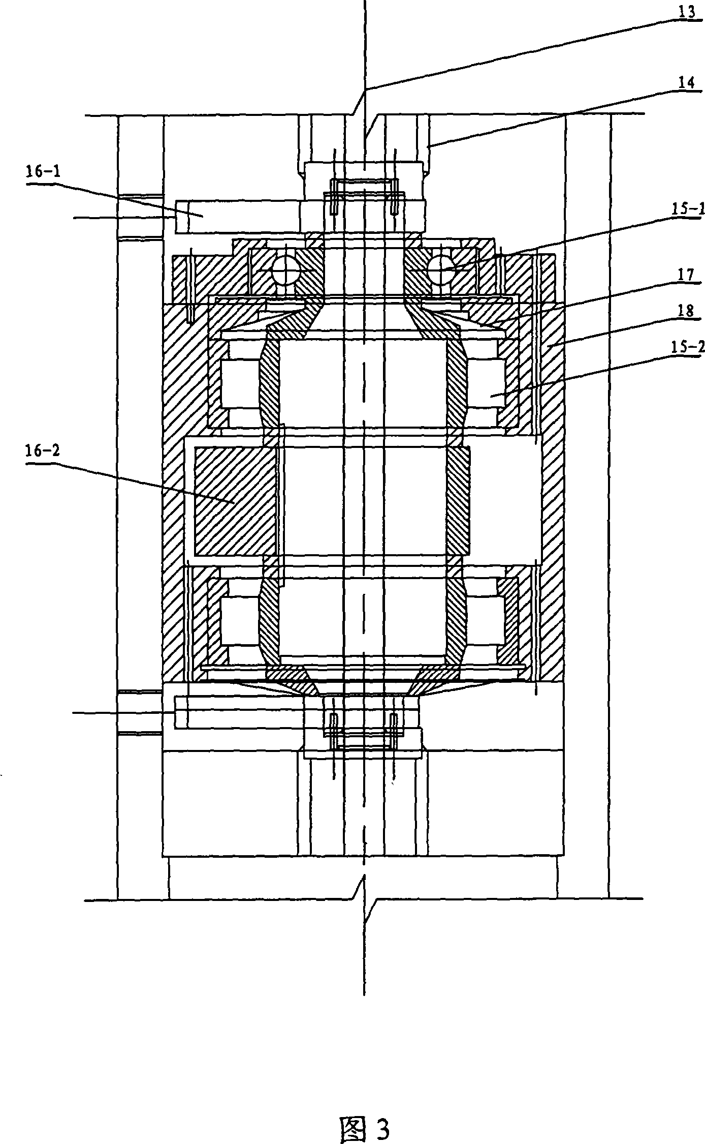
[0024] As shown in Figure 3, it is a schematic diagram of the structure of the eccentric block device, and the described eccentric block device 7 is composed of a pull rod 13, a connecting shaft 14, bearings 15-1, 15-2, ...


PUM


Abstract

The present invention relates to a mandrel vibrating rod for mandrel vibrating machine, which comprises a pressure head cap, an eccentric block device, a central shaft, a sleeve, a locking shoe, a frame and a motor. At least two eccentric block devices pass through the central shaft and are connected inside of the sleeve, the sleeves are connected with each other by the locking shoes, the pressure head cap is arranged at the upper end of the sleeve, the sleeve is arranged vertically on the frame, the bottom of the frame is provided with at least one motor which is connected with the central shaft. The present invention has the advantages of prolonged service life, reduced accident rate, simple maintenance for motor, reduced maintenance costs, shorter time for exchanging fittings, simple disassembly, and reduced maintenance difficulty.

Description

technical field [0001] The invention relates to a core mold vibrating rod used in a core mold vibrating machine, which can be used for producing reinforced concrete drainage pipes and belongs to the technical field of core mold vibrating machines. Background technique [0002] The mandrel vibrating rod is the heart part of the mandrel vibrating machine. By adjusting the frequency of the motor, it generates vibrations with a controllable frequency, drives the vibration of the external mold, and makes the concrete in the mold dense, meeting the production technical requirements of the product. [0003] As shown in Figure 1, it is a schematic diagram of the structure of the German Zubrin core-mode vibrating core-mode vibrating rod, which consists of a locking block 1, a motor 2, an eccentric block 3, a column 4, and a platform 5. There are six motors 2, a total of 18 motors 2 drive the eccentric block 3 to rotate to generate vibration with a controllable frequency, and then dri...

Claims


Application Information

Patent Timeline
Patent Type & Authority Applications(China)
IPC IPC(8): B28B21/16
Inventor 李孟德翁建国
Owner 上海闵马水泥制管有限公司
Why Eureka
Try Eureka