

Upflow type anaerobic reactor
An anaerobic reactor and reactor technology, applied in anaerobic digestion treatment, waste fuel and other directions, can solve the problems of unmaintainable, high sludge concentration, long sludge age, etc., and achieve increased volume and high sludge concentration. , the effect of long sludge age
- Summary
- Abstract
- Description
- Claims
- Application Information
AI Technical Summary
Problems solved by technology
Method used
Image

Examples
Embodiment 1
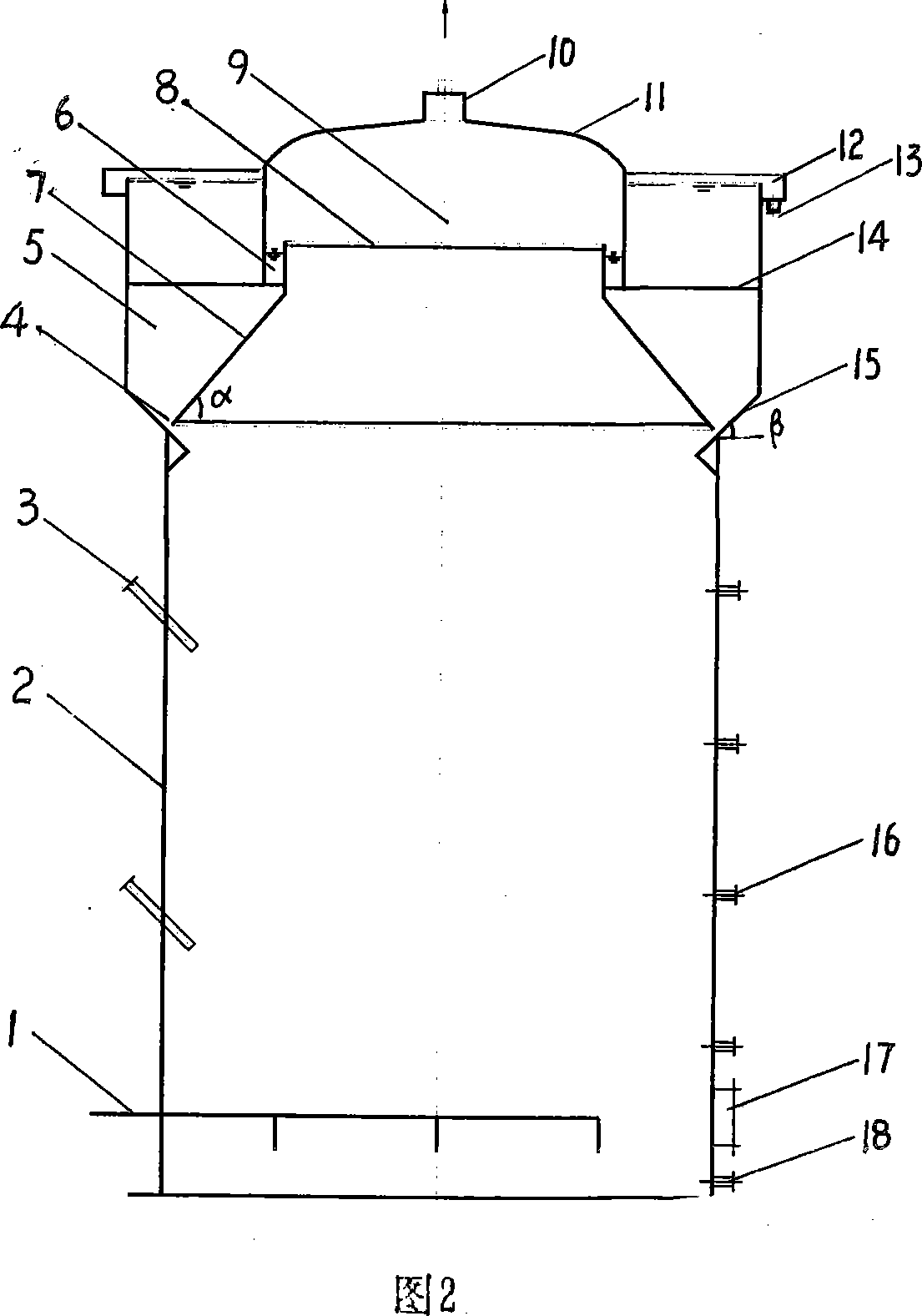
[0035] Embodiment 1: The structure of the present invention is as described above, wherein the diameter of the reactor shell 2 is 3 meters, the diameter of the wide mouth 8 of the conical draft tube is 2 meters, and the angle α of the inclined plate forming the conical draft tube 7 is 45 °, the angle β of reflecting plate 15 is 45 °, the diameter of cylindrical air cover 11 is 2.5 meters, the width of annular passage 6 is 0.25 meters, and the width of annular passage 4 is 0.03 meters. The diameter of the exhaust pipe 10 is 0.08 meters.
Embodiment 2
[0036] Embodiment 2: The structure of the present invention is as described above, wherein the diameter of the reactor cylinder body 2 is 13 meters, and the diameter of the wide mouth 8 of the conical draft tube is 9 meters, and the angle α of the inclined plate that constitutes the conical draft tube 7 is 60° °, the angle β of reflecting plate 15 is 60 °, the diameter of cylindrical air cover 11 is 10 meters, the width of annular channel 6 is 0.5 meter, and the width of annular channel 4 is 0.2 meter. The diameter of the exhaust pipe 10 is 0.4 meters.
Embodiment 3
[0037] Embodiment 3: The structure of the present invention is as described above, wherein the diameter of the reactor shell 2 is 6 meters, the diameter of the wide mouth 8 of the conical draft tube is 4.8 meters, and the angle α of the inclined plate forming the conical draft tube 7 is 50 °, the angle β of reflecting plate 15 is 50 °, the diameter of cylindrical air cover 11 is 5.1 meters, the width of annular passage 6 is 0.15 meters, and the width of annular passage 4 is 0.1 meter. The diameter of the exhaust pipe 10 is 0.2 meters.
PUM
 Abstract
Description
Claims
Application Information