
Device and method for trace to the source for measuring any wave plate retardation

A phase delay and wave measurement technology, which is applied in the field of measuring the phase delay of optical wave plates, can solve problems such as measurement delay, and achieve the effect of compensating system errors and simple operation

Inactive Publication Date: 2007-10-17
TSINGHUA UNIV
View PDF0 Cites 16 Cited by
  • Summary
  • Abstract
  • Description
  • Claims
  • Application Information

AI Technical Summary

Problems solved by technology

Since it is necessary to apply a transverse magnetic field during the measurement and ensure that the direction of the magnetic field is parallel to one of the fast and slow axes of the wave plate, it is impossible to measure the phase delay of any wave plate on a set of devices

Method used


Image

  • Device and method for trace to the source for measuring any wave plate retardation
  • Device and method for trace to the source for measuring any wave plate retardation
  • Device and method for trace to the source for measuring any wave plate retardation

Examples


Embodiment Construction

[0036] 1. Basic principles:

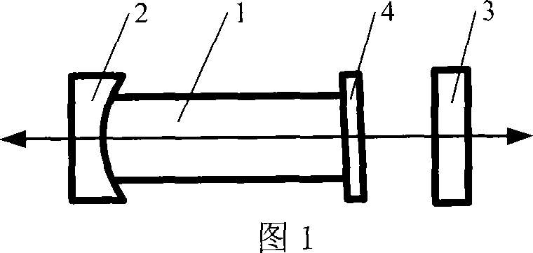
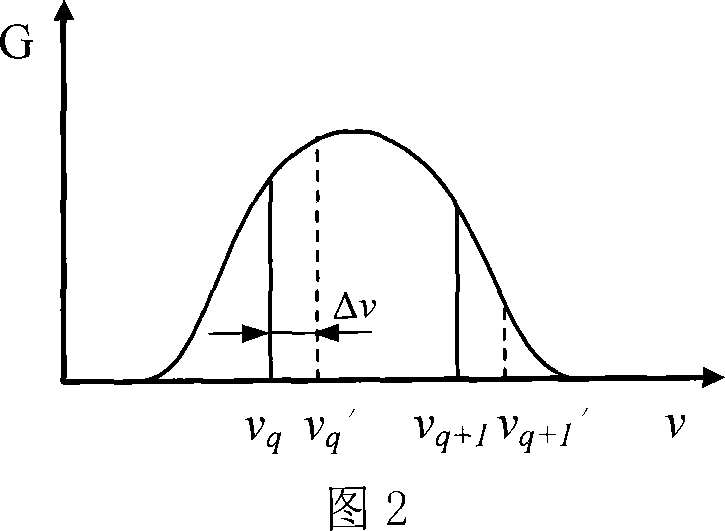
[0037] Fig. 1 is a schematic diagram of a half-cavity He-Ne laser used in a measurement method based on frequency splitting. Among them, the half-cavity laser is composed of a reflector 2, a gain tube 1 and a reflector 3, wherein the two ends of the gain tube 1 are respectively fixed with a reflector 2 and an anti-reflection window 4, and the resonant cavity is formed by the reflectors 2 and 3. Two adjacent longitudinal modes ν of the laser q 、ν q+1 The frequency difference between the longitudinal mode spacing is

[0038] Δ = c 2 L - - - ( 1 )

[0039] Where c is the speed of light, and L is the length of the resonant physical cavity.

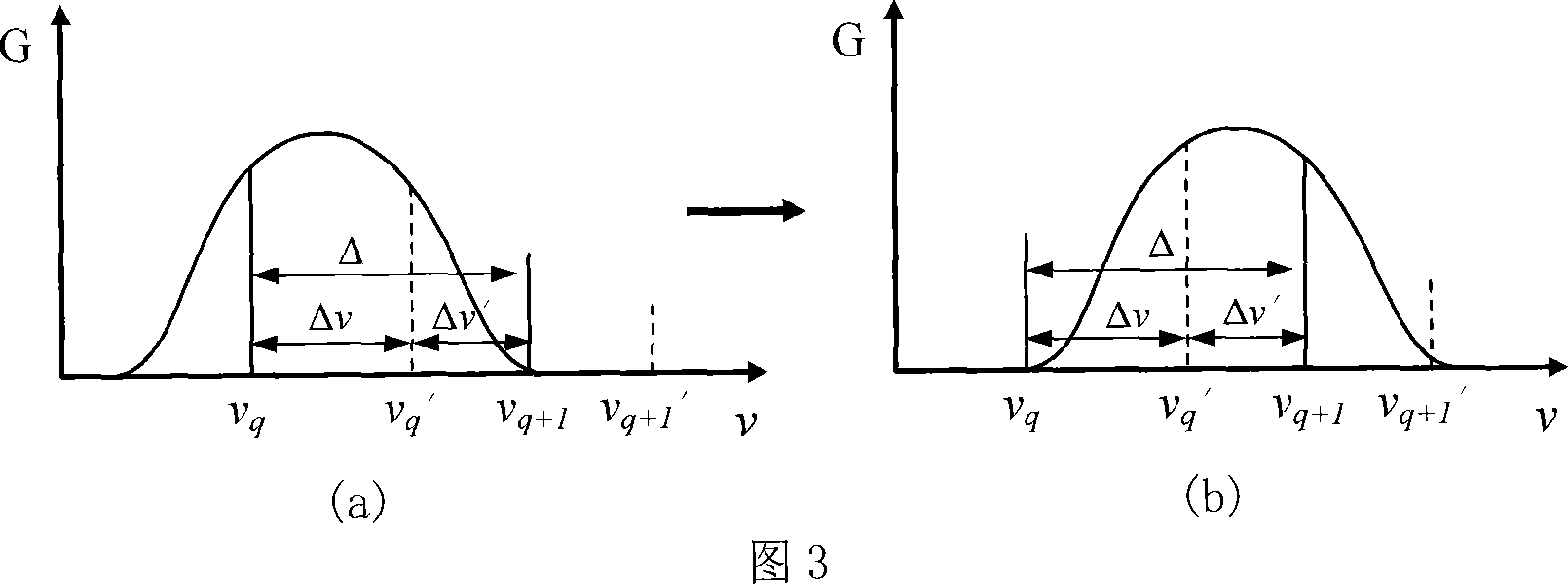
[0040] When a birefringent element is placed in the resonator, the longitudinal mode output by the laser will split, and each original longi...


PUM


Abstract

The invention discloses a method and apparatus capable of measuring phase delay of arbitrary wave plate including half-wave plate and full-wave plate, characterized in that using separately longitudinal mode direct-reading method, additive wave plate generated phase offset method and frequency splitting method aimed at the wave plate of different phase delay range to measure, therefore solving the problem of incapability of measuring the half / full wave plate using the frequency splitting based method for measuring phase delay of wave plate. In order to improve the measurement accuracy, the invention compensates separately for the system error produced by inclined installation of wave plate and anisotropy caused by laser intracavity residual stress. The invention is capable of measuring arbitrarily wave plates in a system with high measurement accuracy, simplicity and low costs, obtaining the laser wavelength by wave plate phase delay through measuring laser frequency, providing reference for other wave plate measurement methods.

Description

technical field [0001] The invention relates to the technical field of laser measurement, in particular to a method and a device for measuring the phase delay of an optical wave plate. Background technique [0002] Waveplates are used in many optical systems involving polarized light. Phase delay is the most important technical index, which greatly affects the performance of the system in applications. Therefore, it is very important to accurately measure its phase delay. The measurement accuracy of the commonly used wave plate phase delay measurement method is generally about 0.5 degrees to 1 degree, and the equipment adjustment is more complicated. Some require high-precision goniometers or standard quarter-wave plates; some are only suitable for quarter-wave plates and not for half-wave plates. In addition, existing measurement methods cannot be traced to natural references, which make it difficult to meet the increasing measurement requirements. [0003] The method of ...

Claims


Application Information

Patent Timeline
Patent Type & Authority Applications(China)
IPC IPC(8): G01J9/00
Inventor 张书练刘维新
Owner TSINGHUA UNIV
Learn More