
Aluminum pipe production method

A manufacturing method and technology for aluminum tubes, applied in the field of aluminum tube manufacturing, can solve the problems of decreased dimensional accuracy, protruding aluminum slag defects, difficult productivity, etc., and achieve the effects of easy size control, preventing protruding defects and reducing production costs

Inactive Publication Date: 2007-10-17
RESONAC HOLDINGS CORPORATION
View PDF2 Cites 3 Cited by
  • Summary
  • Abstract
  • Description
  • Claims
  • Application Information

AI Technical Summary

Problems solved by technology

Therefore, this method is not only not efficient enough but also difficult to fundamentally solve problems such as low productivity and high production costs.
[0017] On the other hand, in the aluminum pipe manufacturing method as disclosed in Patent Document 3, since the surface of the aluminum pipe is removed (certain thickness) before the stretching treatment and becomes flat, the removed debris (aluminum slag) is likely to be re-adhered. Attached to the surface of the original aluminum pipe so that the aluminum slag that is removed can cause a blemish raised after the stretching process, which causes image blemishes
Therefore, it is difficult to achieve (image) high quality
In addition, in this method, since the surface of the original aluminum pipe is removed by a certain thickness, the removal of the surface causes a reduction in diameter
As a result, it is difficult to control the tube diameter, and thus, the (image) quality decreases due to a decrease in dimensional accuracy

Method used


Image

  • Aluminum pipe production method
  • Aluminum pipe production method
  • Aluminum pipe production method

Examples


example 1

[0117] An aluminum raw pipe having an outer diameter of 32 mm formed by hot extrusion was cut to a length of 2,500 mm. Then, in the dross removal step, aluminum dross adhering to the surface of the aluminum raw pipe is removed.

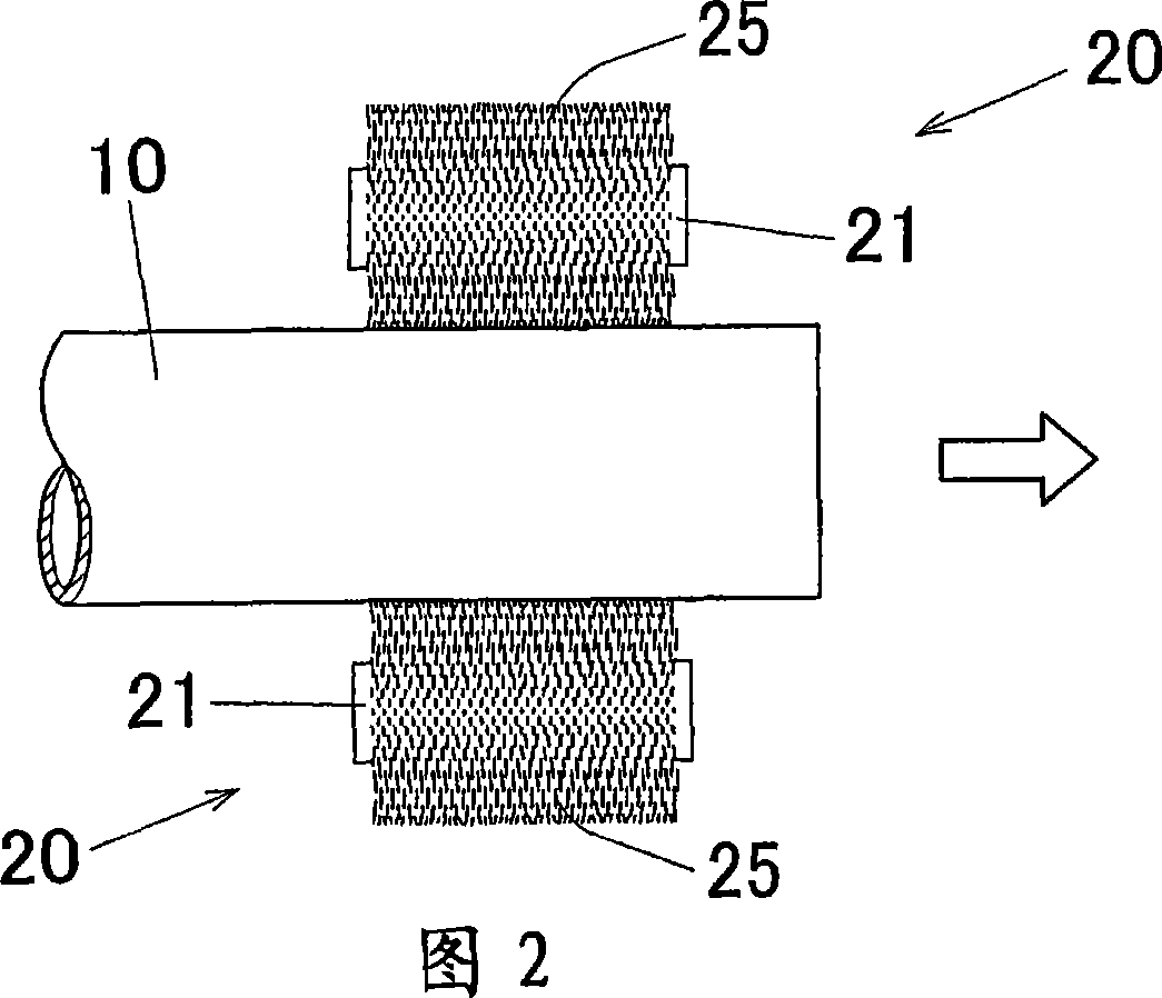
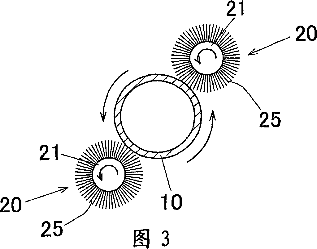
[0118] In this scum removal step, similarly to the method shown in FIG. 4 , the same wiping roll 20 as that used in the above-described embodiment is used, in which a brush 25 is wound on the outer peripheral surface of a mandrel 21 .

[0119] The hair of the brush 25 used was "Multi-nylon" (trademark) manufactured by Showa Kogyo Kabushiki Kaisha, the length of the hair was 50 mm, and the diameter was 25 μm.

[0120] The outer diameter of the mandrel 21 is 30 mm, and the overall diameter of the erasing roller 20 is 130 mm.

[0121] The two wiping rollers 20 described above were prepared. Use a device similar to that shown in Figures 2 and 3 to wipe off the aluminum slag adhering to the outer peripheral surface of the aluminum original pipe 10 with a...

example 2

[0125] As shown in FIG. 5 , in the dross removal step, aluminum dross was removed using a wiping tape made of a wipe (“Berima” (trademark) supplied by Kanebo Gohsen, Ltd.).

[0126] The width of the erasing tape is 300mm, the transmission speed of the erasing tape is 10cm / min, the contact length of the erasing tape relative to the original aluminum tube is 10mm, and the contact pressure is 10g / cm 2 .

[0127] Except for this, in the same manner as in Example 1 above, an aluminum tube for a photosensitive drum base was produced. Then, the area and distribution frequency of the aluminum dross elongated pieces were measured (FIG. 7).

example 3

[0129] In the same manner as in Example 1, an aluminum tube for the photosensitive drum substrate was manufactured and the area and distribution frequency of the elongated pieces of aluminum slag were measured (Fig. 8), except that a polyurethane sponge with a thickness of 50 mm was used to wrap around 30mm wiping roller on the outer peripheral surface of the mandrel.


PUM

PropertyMeasurementUnit
diameteraaaaaaaaaa
lengthaaaaaaaaaa
lengthaaaaaaaaaa

Abstract

The invention is directed to an aluminum pipe product method comprising an extrusion step for obtaining an aluminum raw pipe (10) and a drawing step for executing a drawing process of the aluminum raw pipe (10). Before executing the drawing step, a slug removing step for removing aluminum slugs (1) adhering to a surface of the aluminum raw pipe (10) is executed by rubbing off the aluminum slugs (1). This can provide an aluminum pipe production method capable of preventing generation of defect protrusions while improving the productivity.

Description

[0001] This application claims priority from Japanese Patent Application No. 2004-325213, filed November 9, 2004, and U.S. Provisional Application S.N. 60 / 627,946, filed November 16, 2004, the entire disclosures of these priority applications are incorporated Here for reference. [0002] Cross References to Related Applications [0003] This application is filed pursuant to 35 U.S.C. §111(a) and is required under 35 U.S.C. §119(e)(1) of U.S. Provisional Application S.N.60 / 627,946 filed November 16, 2004 under 35 U.S.C. §111(b) Filing date benefits. technical field [0004] The present invention relates to a method of manufacturing an aluminum tube used as a photosensitive drum for a copier or an electrophotographic device such as a laser printer or a facsimile, and related technologies. [0005] In this specification and claims, the term "aluminum (Al)" refers to aluminum and its alloys. Background technique [0006] The following description illustrates the inventor's un...

Claims


Application Information

Patent Timeline
Patent Type & Authority Applications(China)
IPC IPC(8): B21C1/22G03G5/10B21C23/08G03G21/00B23B29/00
CPCB21C37/30B21C43/00Y10T29/5199Y10T442/30B21C1/22Y10T442/60B21C23/085G03G5/102Y10T29/49755B21C37/06
Inventor 滨野秀光金山孝范宫崎雅洋
Owner RESONAC HOLDINGS CORPORATION
Learn More