A floor-mounted curve groove type elliptic plane monopolar antenna
A monopole antenna and curved slot technology, applied in the microwave field, can solve the problems of large antenna size and difficult to meet the requirements of miniaturization of mobile communication, and achieve the effects of expanding bandwidth, improving performance, and improving impedance characteristics
- Summary
- Abstract
- Description
- Claims
- Application Information
AI Technical Summary
Problems solved by technology
Method used
Image
Examples
Embodiment 1
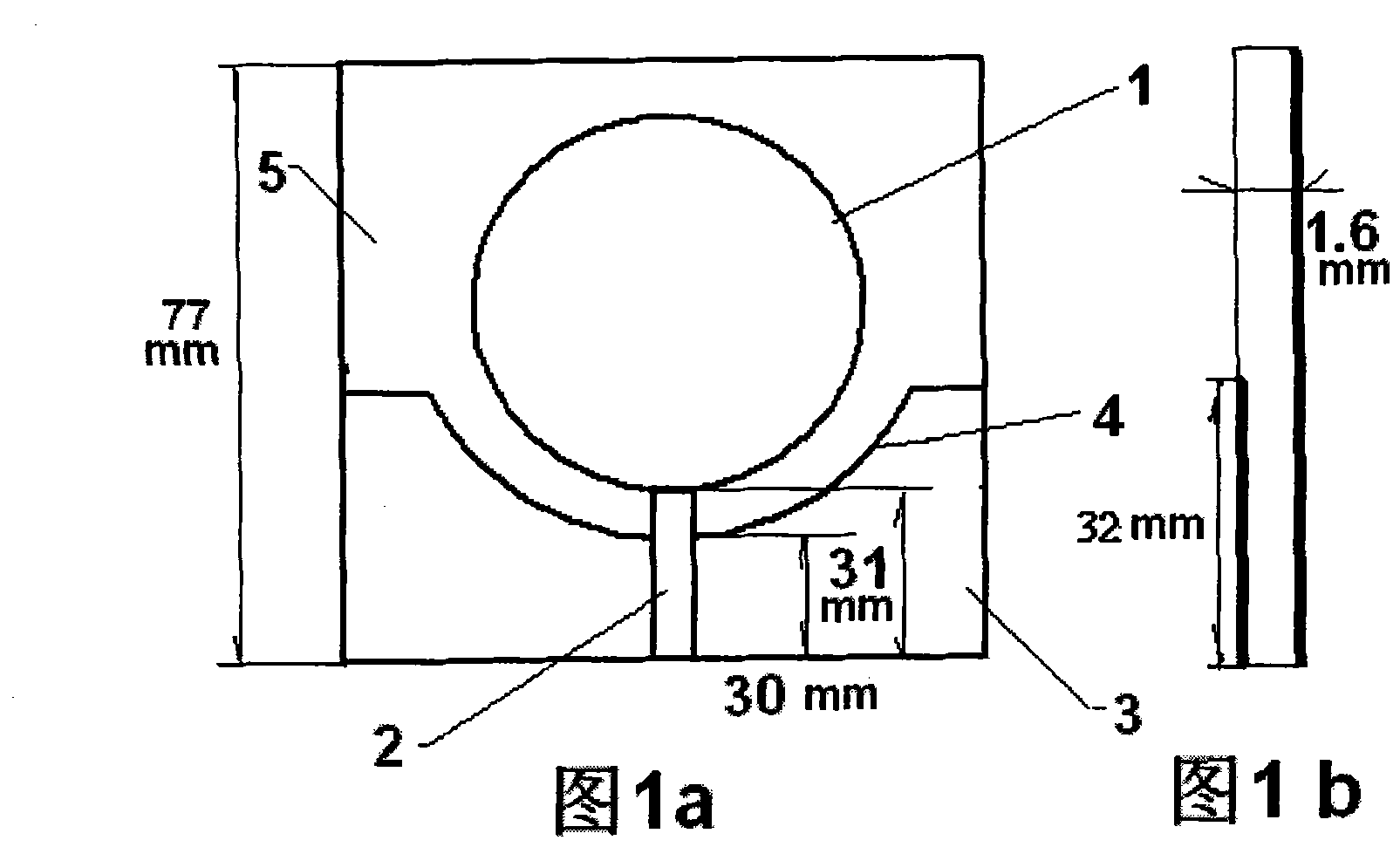
[0017] Embodiment 1: as Figure 1a , Figure 1b As shown, antenna (1); microstrip feeder (2); floor (3); arc groove (4); dielectric plate (5), Figure 1a , Figure 1b The structure and parameters of the curved slot elliptical planar monopole antenna on the floor (3) are given. The floor (3) has an arc-shaped groove (4), and the edge of the arc-shaped groove (4) is parallel to the edge of the antenna (1) of the oval plane monopole. Different floor bending groove structures can be obtained by changing its structural parameters. In order to prove the change of the floor bending groove structure to the performance of the antenna (1) and to understand the effect of different structures, the comparison of the return loss on different floor structures under two operating frequencies was calculated by simulation software, as shown in Table 1. The specific structure is set as follows Figure 5 , 6 , shown in 7: the dielectric constant of the medium ε=3.43, the width of the microstr...
Embodiment 2
[0023] When designing an antenna (1) with an elliptical or circular plane monopole, use the floor arc groove structure, cut the arc groove (4) on the floor (3), and the edge of the arc groove (4) and The edges of the antenna (1) are parallel, and the size of the arc-shaped groove (4) is adjusted to achieve the best effect, so as to improve the radiation performance of the antenna (1). Numerical calculation results;
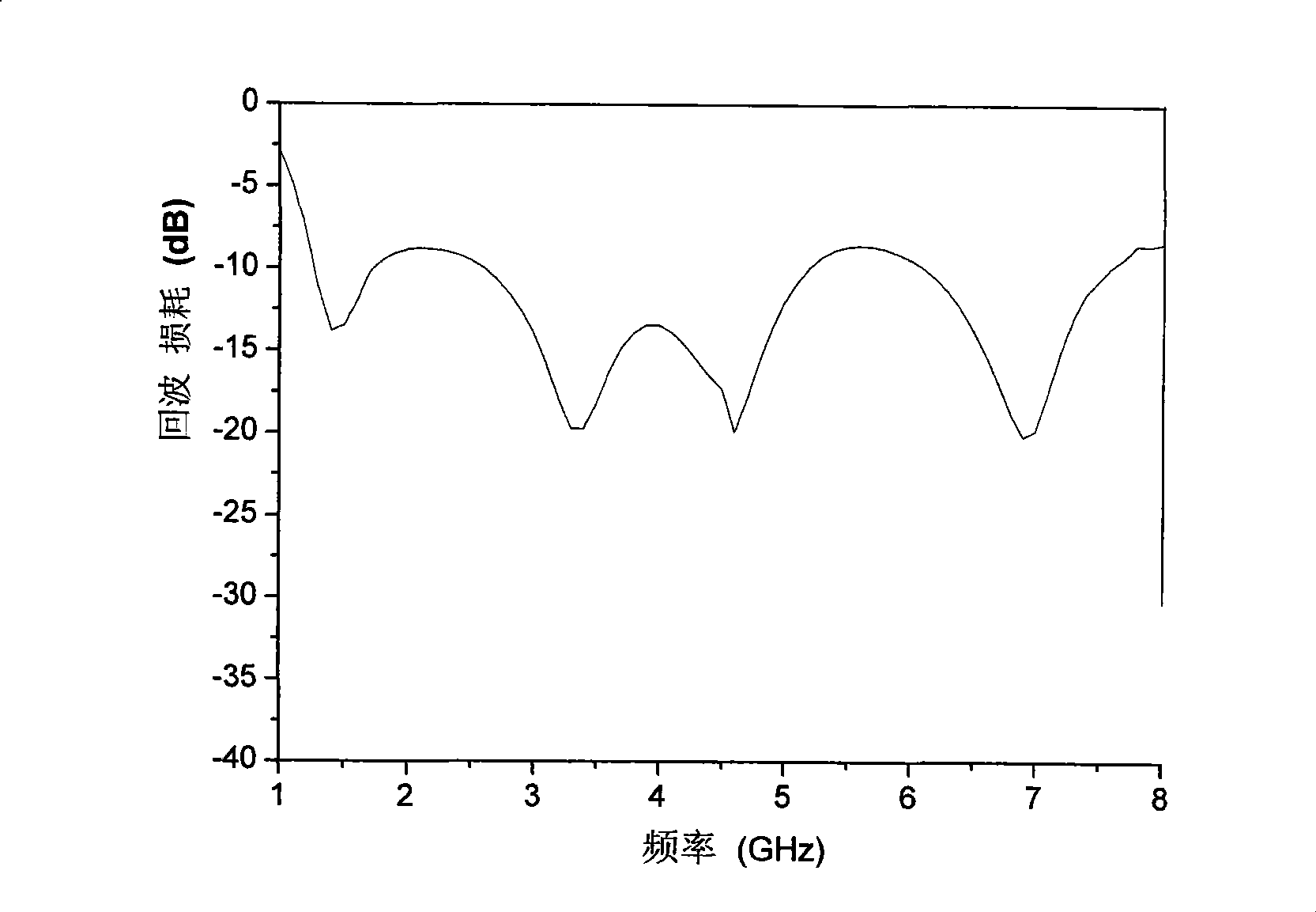
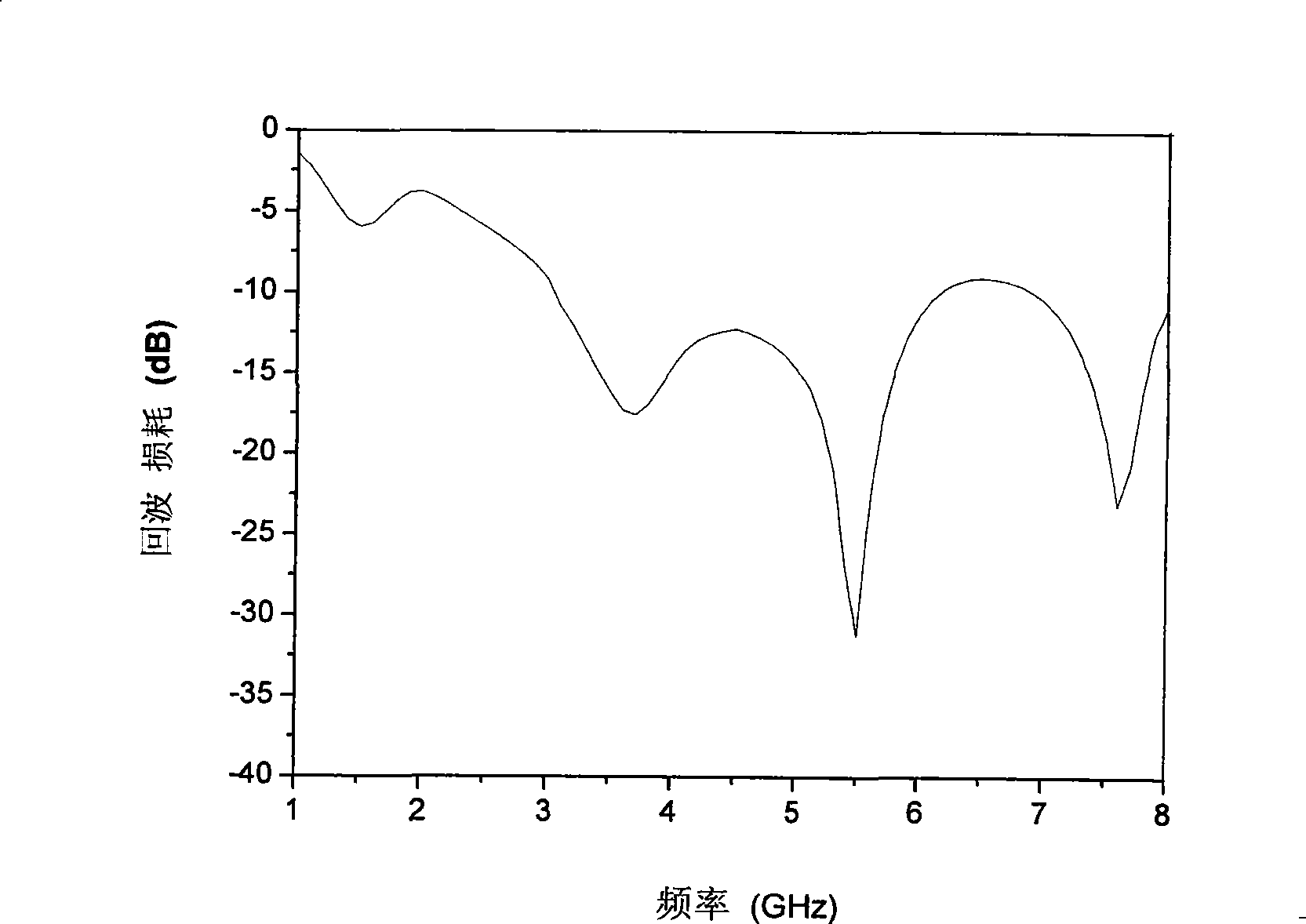
[0024] A1, A2 and B were simulated with simulation software, figure 2 , image 3 , Figure 4 The S of these three structures are given respectively 11 The magnitude of the parameter varies with frequency. Figure 8 The curves of the three structures were compared, by Figure 8 It can be seen that, compared with A1 and A2, the reflection coefficient S 11 significantly reduced, indicating that the use of the floor arc groove (4) structure parallel to the edge of the antenna (1) (elliptical) radiation sheet can improve the performance of the circular or ellipt...
PUM
 Abstract
Description
Claims
Application Information
 - R&D
- Intellectual Property
- Life Sciences
- Materials
- Tech Scout
- Unparalleled Data Quality
- Higher Quality Content
- 60% Fewer Hallucinations
Browse by: Latest US Patents, China's latest patents, Technical Efficacy Thesaurus, Application Domain, Technology Topic, Popular Technical Reports.
© 2025 PatSnap. All rights reserved.Legal|Privacy policy|Modern Slavery Act Transparency Statement|Sitemap|About US| Contact US: help@patsnap.com


