Micro-optical fiber ring dye laser with evanescent wave coupling gain

A dye laser and micro-fiber technology, applied in the field of micro-optical components, can solve the problems of difficult application, unstable structure, unfavorable optical integration, etc., and achieve the effect of simple preparation and easy integration

Inactive Publication Date: 2007-10-24
ZHEJIANG UNIV
View PDF0 Cites 10 Cited by
  • Summary
  • Abstract
  • Description
  • Claims
  • Application Information

AI Technical Summary

Problems solved by technology

However, these structures are not stable enough, which is not conducive to optical integration, and it is difficult to apply them in practice.

Method used


Image

  • Micro-optical fiber ring dye laser with evanescent wave coupling gain
  • Micro-optical fiber ring dye laser with evanescent wave coupling gain
  • Micro-optical fiber ring dye laser with evanescent wave coupling gain

Examples


Embodiment Construction

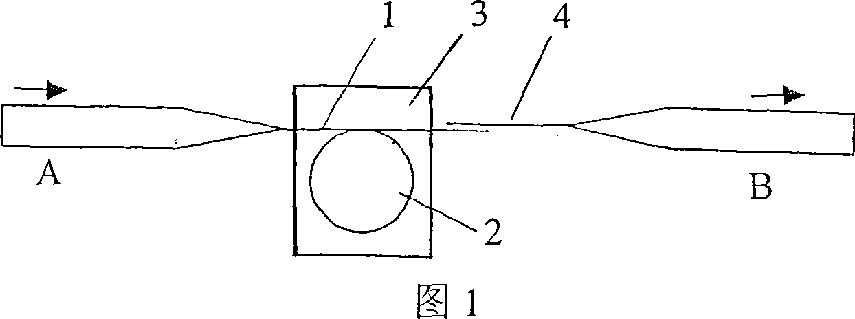
[0011] As shown in Figure 1, the present invention is prepared into ring junction resonator 2 with the first microfiber 1, and one end of ring junction resonator 2 is connected with single-mode optical fiber, and the other end of ring junction resonator 2 is connected with second microfiber 4 coupling, the ring junction resonator 2 is immersed in the solution 3 doped with the gain medium, and the gain medium is excited by the evanescent wave distributed on the surface of the micro-fiber to generate laser light.

[0012] The diameter of the micro-fiber is 0.5-5 μm. The ring junction laser has a diameter of 50 μm to 10 mm. The ring junction resonator is a ring single junction resonator. The gain medium mixed with rhodamine 6G dye solution, rhodamine B dye solution or quantum dot solution.

[0013] The preparation process of the present invention is as follows:

[0014] (1) Firstly, a single-mode optical fiber is drawn by a high-temperature stretching method to prepare a micro...


PUM


Abstract

The disclosed micro-fiber circular-junction dye laser with swift-away wave coupled gain comprises: using a first micro-fiber to prepare circular-junction resonant cavity with two ends connected with a mono-mode fiber and second micro-fiber respectively; dipping the resonant cavity into a solution doped gain medium to generate laser and output from the second micro-fiber. This invention is small-size, stable and convenient to be integrated.

Description

technical field [0001] The invention relates to micro-optical elements, in particular to a micro-fiber ring-junction dye laser utilizing evanescent wave coupling gain. Background technique [0002] Microlaser is an important optoelectronic device, which has broad application prospects in optical information processing, as well as biological and chemical sensing. With the improvement of the optical fiber preparation process, low-loss micro-nano fibers have been prepared and have been applied to the production of micro-nano photonics devices. Micro-fiber ring junction resonators and rare earth-doped micro-fiber ring junction lasers have been proven. The miniature lasers that utilize evanescent wave coupling gain that have been realized in the world mainly include spherical and cylindrical structures. However, these structures are not stable enough for optical integration and difficult to be applied in practice. Contents of the invention [0003] The object of the present i...

Claims


Application Information

Patent Timeline
Patent Type & Authority Applications(China)
IPC IPC(8): H01S3/20H01S3/083H01S3/067
Inventor 童利民姜校顺杨青
Owner ZHEJIANG UNIV
Why Eureka
Try Eureka