

Transformer-free ultrasonic motor driver
A technology of ultrasonic motor and driver, applied in the direction of generator/motor, piezoelectric effect/electrostrictive or magnetostrictive motor, electrical components, etc., can solve the problems of high cost, large volume, poor adaptability, etc., and achieve cost Low profile, small size, and strong load capacity
- Summary
- Abstract
- Description
- Claims
- Application Information
AI Technical Summary
Problems solved by technology
Method used
Image

Examples
specific Embodiment approach 1
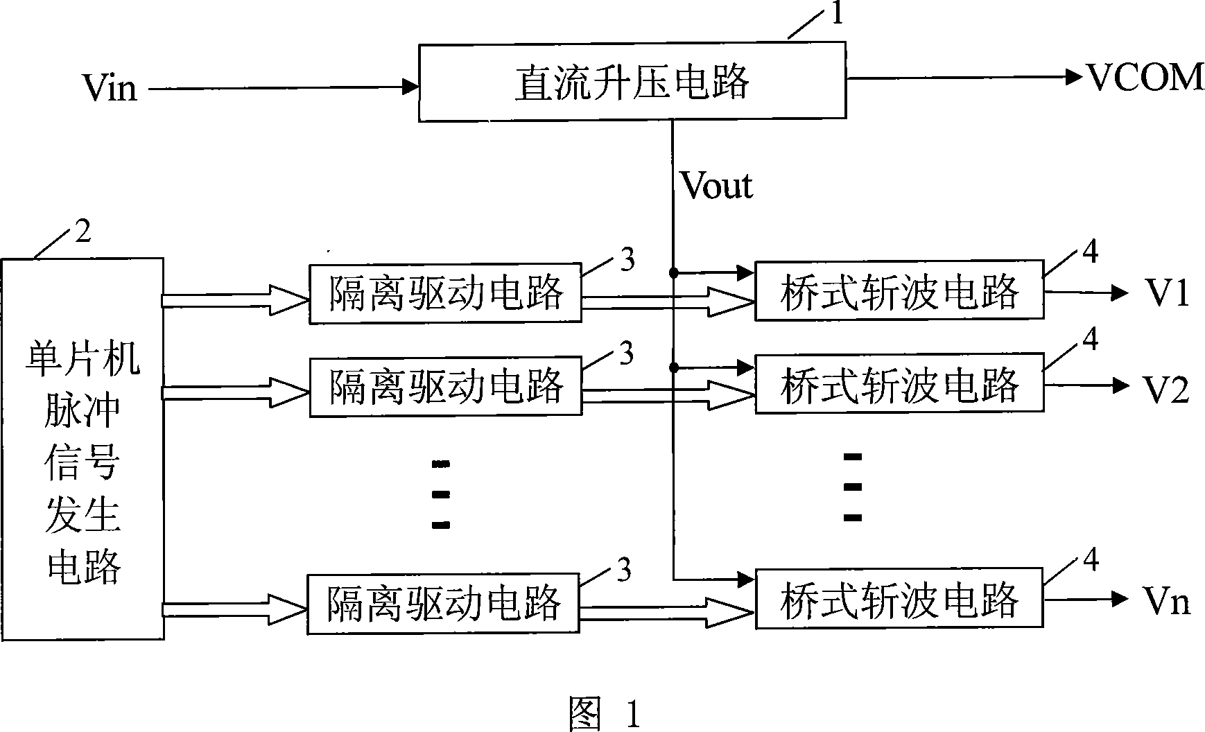
[0007] Specific Embodiment 1: Refer to FIG. 1 to illustrate this embodiment. In this embodiment, the ultrasonic motor driver without a transformer is composed of a single-chip pulse signal generating circuit 2, a DC boost circuit 1, a multi-channel isolation drive circuit 3 and a multi-channel bridge chopper circuit 4. The single-chip pulse signal generating circuit 2 contains the same The multi-channel pulse signal output terminals of frequency, duty cycle and phase difference are respectively connected to the signal input terminals of multiple isolated drive circuits 3, and the signal output terminals of each isolated drive circuit 3 are connected to the control signals of each bridge chopper circuit 4. The input terminal is connected, and the two power supply terminals of each bridge chopper circuit 4 are connected in parallel between the DC drive voltage output terminal Vout of the DC boost circuit 1 and the power ground, and each bridge chopper circuit 4 outputs one pulse ...
specific Embodiment approach 2
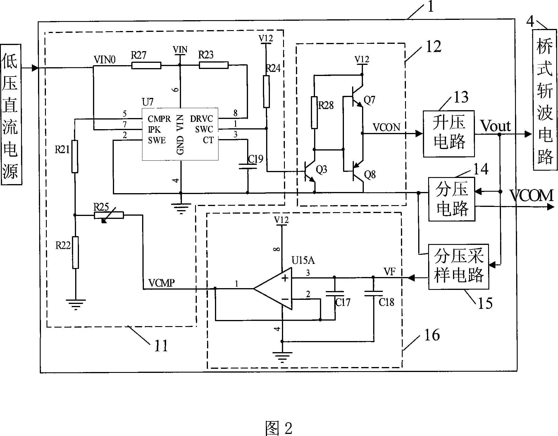
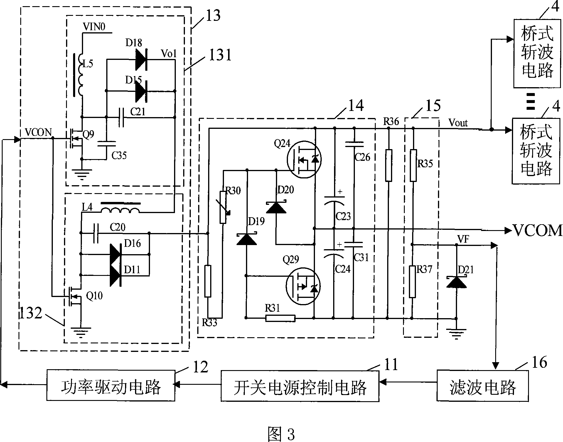
[0010] Specific Embodiment 2: Refer to FIG. 2 and FIG. 3 to illustrate this embodiment. The difference between this embodiment and the transformerless ultrasonic motor driver described in Embodiment 1 is that the DC boost circuit 1 is composed of a switching power supply control circuit 11, a power drive circuit 12, a filter circuit 16, a boost circuit 13, and Voltage circuit 14 and voltage division sampling circuit 15, the control signal output end of the switching power supply control circuit 11 is connected with the signal input end of the power drive circuit 12, the signal output end of the power drive circuit 12 is connected with the control signal of the booster circuit 13 The input terminal is connected, and the DC voltage output terminal output of the booster circuit 13 is equal to the DC drive voltage Vout of the peak-to-peak value of the ultrasonic motor drive signal to the power input terminal of the bridge chopper circuit 4, and the two power supply terminals of the...
specific Embodiment approach 3
[0019] Specific Embodiment Three: Refer to FIG. 4 to illustrate this embodiment. The isolated drive circuit 3 in this embodiment adopts the isolation drive chip IR2104 dedicated to field effect transistors. The bridge chopper circuit 4 is an electric bridge composed of two N-type field effect transistors. The two power terminals of the bridge chopper circuit 4 Connect respectively with the DC voltage output terminal of the DC boost circuit 1 and the power supply ground, and the signal input terminal of the isolation drive circuit 3 is connected with the pulse signal output terminal of the single-chip pulse signal generating circuit 2 containing the same frequency, duty cycle and phase difference, The signal output end of the isolation drive circuit 3 is connected to the control signal input end of the bridge chopper circuit 4 .
[0020] The dedicated drive chip for field effect transistors described in this embodiment selects an IR2104 type integrated circuit.
PUM
 Abstract
Description
Claims
Application Information