Wind-cooling heat dissipating method of CT device and the apparatus thereof

A technology of heat dissipation device and heat dissipation method, which is applied to the cooling of instruments, radiation safety devices, and parts of instruments, etc., and can solve problems such as noise pollution, noise increase, and negative effects

Active Publication Date: 2007-10-31
SIEMENS SHANGHAI MEDICAL EQUIP LTD
View PDF0 Cites 25 Cited by
  • Summary
  • Abstract
  • Description
  • Claims
  • Application Information

AI Technical Summary

Problems solved by technology

Yet along with the raising of described fan rotating speed or the increase of quantity, the noise in it also increases rapidly, and the noise of badly designed CT equipmen

Method used


Image

  • Wind-cooling heat dissipating method of CT device and the apparatus thereof
  • Wind-cooling heat dissipating method of CT device and the apparatus thereof
  • Wind-cooling heat dissipating method of CT device and the apparatus thereof

Examples


Embodiment Construction

[0022] The air-cooled heat dissipation method and device of the present invention are described by taking the application on CT equipment as an example, but its application is not limited to this, and other medical imaging equipment that needs heat dissipation, such as nuclear magnetic resonance equipment, etc., can also be applied All or part of the design points of the present invention are used to realize the purpose of heat dissipation and noise reduction.

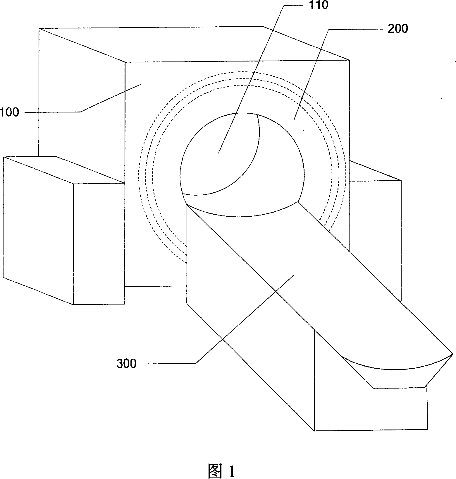
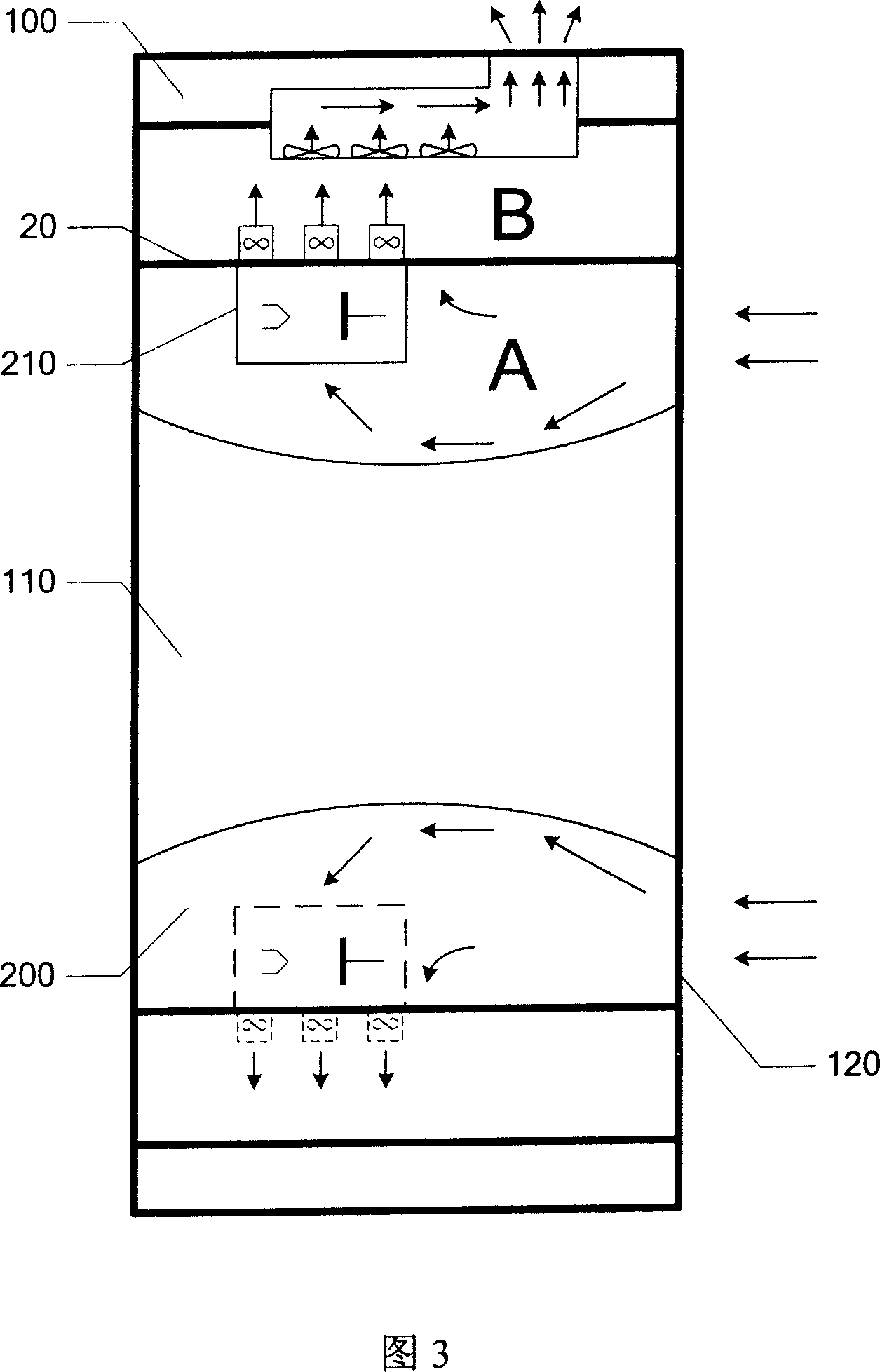
[0023] Referring to Fig. 3, a typical CT equipment includes a frame 100, and a turntable 200 rotating in the frame 100 for scanning inspection, wherein a frame hole 110 is set in the frame 100, and the turntable 200 surrounds the frame The hole 110 is rotated. The patient lies on a hospital bed arranged in front of the frame 100 and enters the hole 110 of the frame to be scanned.

[0024] The air-cooled heat dissipation method and device of the CT equipment of the present invention will be described in detail below in...


PUM


Abstract

The invention discloses an air-cooled heat radiating method of CT device and apparatus, which is characterized by the following: entering cold air into bay from inlet port; heat-exchanging with the heating element in the bay; discharging out of the bay through outlet port; separating the bay as mutual independence first section and second section; placing the heating element in the first section; entering the cold air into the first section from the inlet port; heat-exchanging with the heating element; discharging the hot air to the second section; discharging out of the bay from the outlet port. This invention optimizes cool approach of air-cooled heat radiation effectively.

Description

technical field [0001] The present invention relates to a heat dissipation method and device for computerized tomography (Computed Tomography; "CT" for short) equipment, in particular to an air-cooled heat dissipation method and device for CT equipment. Background technique [0002] CT equipment is a complex diagnostic system composed of X-ray emitting tubes, detectors, calibrators, high-voltage generators and many other sophisticated electrical and physical equipment. These electro-physical devices are mounted on a high-speed rotating turntable and sealed by a set of casings to avoid contact with doctors or patients. These electrical and physical devices mentioned above have very high requirements for their operating environment, for example, the temperature of the cooling oil in the bulb tube must not exceed 80 degrees, and the external temperature of the detector must not exceed 40 degrees. However, some components generate tens of kilowatts of heat during operation, suc...

Claims


Application Information

Patent Timeline
IPC IPC(8): A61B6/03A61B6/10G12B15/04
Inventor 赵文江
Owner SIEMENS SHANGHAI MEDICAL EQUIP LTD
Why Eureka
Try Eureka