Node component used for connecting steel tube concrete column with building roof beam

A technology for concrete-filled steel tubular columns and nodes, which is applied in building structures, buildings, etc., can solve the problems of excessively large cross-section of steel ring plates, difficult construction, and difficult to control the center of gravity of hoisting, so as to improve shear resistance, reduce dome extension effect, Enhance the effect of beam-column connections

Active Publication Date: 2010-12-15
ARCHITECTURAL DESIGN RES INST OF GUANGDONG PROVINCE +1
View PDF8 Cites 0 Cited by
  • Summary
  • Abstract
  • Description
  • Claims
  • Application Information

AI Technical Summary

Problems solved by technology

[0007] 1) The section of the steel ring plate is too large, and the joint force transmission mainly depends on the force transmission of the steel ring plate, mainly the horizontal ring plate connected with the upper and lower edges of the steel corbel. The general horizontal ring plate section is not less than 150mm
After the nodes are covered with concrete, the volume is relatively large, which affects the building space;
[0008] 2) The steel ring plate is relatively wasteful. The stress of the horizontal ring plate is the place where the ring plate meets the steel corbel, and the rest of the ring plate has not reached the stress level of this place, and the uniform ring diameter is wasteful;
[0009] 3) The connection between the steel corbel and the floor beam is unstable and easy to slide: ordinary steel corbel shear studs cannot prevent sliding well when the floor beam is pulled outward;
[0010] 4) The layout of the floor frame beams is inflexible, and the cross-section and elevation of the floor frame beams are limited by the elevation and spacing of the horizontal ring slabs. It is difficult to deal with the situation of unequal beam heights and unequal elevations;
[0011] 5) There are difficulties in construction. The steel corbels and steel pipe columns are hoisted together, which not only requires higher lifting requirements for the tower crane, but also makes it more difficult to control the hoisting center of gravity
[0014] 1) The force transmission of the joints is not clear, the connection between the ring beam and the steel pipe wall is unreliable, the mechanical properties are close to hinge joints, and the safety is insufficient;
[0015] 2) The section of the ring beam is too large, and the force transmission of the joints mainly depends on the force transmission between the ring beam and the steel pipe wall. The quality of the section of the ring beam is high, and the section is too large, which causes the cost of the floor and foundation to increase, and the building space to decrease, which is not beautiful. And seriously affect the arrangement of equipment pipelines down the column

Method used


Image

  • Node component used for connecting steel tube concrete column with building roof beam
  • Node component used for connecting steel tube concrete column with building roof beam
  • Node component used for connecting steel tube concrete column with building roof beam

Examples


Embodiment 1

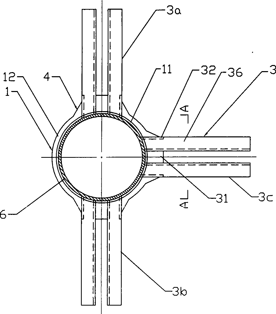
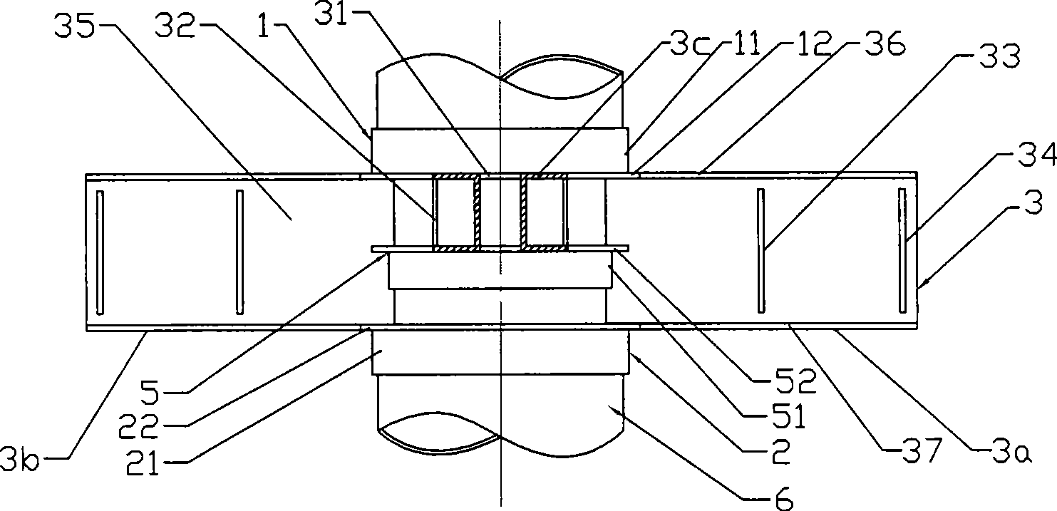
[0039] A specific implementation of the node component used to connect the steel pipe concrete column and the floor beam according to the present invention is as follows: figure 1 ,figure 2, Figure 4 As shown, the node member includes a steel pipe 6 and three steel corbels 3a, 3b, 3c arranged in a "T" shape at intervals of 90° along the horizontal plane, and the three steel corbels 3a, 3b, 3c have different heights in the vertical direction layout.

[0040]The upper flange 36 and the lower flange 37 at the root of the three steel corbels 3a, 3b, 3c are provided with horizontal stiffeners 31, and between the upper flange 36 and the lower flange 37 there is a The vertical stiffening plate 32, the above-mentioned horizontal stiffening plate 31, the vertical stiffening plate 32 and the upper flange 36 and the lower flange 37 at the root of the steel corbels 3a, 3b, 3c jointly form a box-type structure. The side walls of the webs 35 of the steel corbels 3a, 3b, 3c are provided w...

Embodiment 2

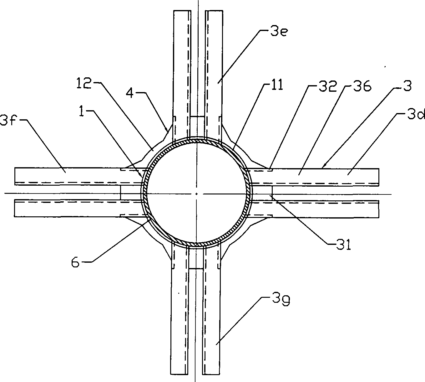
[0043] A specific implementation of the node component used to connect the steel pipe concrete column and the floor beam according to the present invention is as follows: image 3 , Figure 4 As shown, the difference from the previous embodiment is that the node members include steel pipes 6 and are spaced 90 along the horizontal plane in a "ten" shape. The four steel corbels 3d, 3e, 3f, 3g are arranged, and the four steel corbels 3d, 3e, 3f, 3g are arranged at the same height in each direction; the node member also includes only one upper ring plate 1 and one lower ring plate 2 ring plate assembly; the upper ring plate 1 and the lower ring plate 2 are full ring structures with the same structure: the vertical ring plates 11, 21 are cylindrical shapes compatible with the steel pipe 6, and the horizontal ring plates 12, 22 is a full circle, the upper ring plate 1 and the lower ring plate 2 are coaxial and arranged oppositely, and the roots of the four steel corbels 3d, 3e, 3f,...

Embodiment 3

[0045] A node member for connecting concrete filled steel pipe columns and floor beams according to the present invention is specifically implemented as follows Figure 4 , Figure 5 , as shown in Figure 6, different from Embodiment 1, the node members include steel pipes 6 and three steel corbels 3h, 3i, 3j arranged at intervals in a "Y" shape along the horizontal plane, which are arranged at different heights in each direction; the nodes The component also includes a ring plate assembly consisting of an upper ring plate 1 and two lower ring plates 2, 5; the upper ring plate 1 and one of the lower ring plates 2 are full ring structures with the same structure, and one of the steel corbels The protruding end of the upper web 35 at the root of 3h is inserted and welded to the upper ring plate 1 and the two horizontal ring plates 12, 22 of one of the lower ring plates 2; the other lower ring plate 5 is located on the above-mentioned upper ring plate 1 Between one of the lower r...


PUM


Abstract

The invention a juncture structure used in connecting the steel pipe concrete post and the building coping, comprising a steel and fixed arranged juncture structure, all the juncture structure comprising an annual board structure and a steel cow leg component, the annual board component comprises more than one upper annual board and one lower annual board that the longitudinal cross-section are Lshaped, composed by the vertical annual board and the horizontal annual board turned outside, the upper annual board and the lower annual board is fixed connected with the outer wall of the steel pipe, the steel cow leg component is horizontally placed, comprising more than one steel cow leg, one end of the steel cow leg is fixed connected with the annual board component and the outer wall of thesteel pipe, another end of the steel cow leg is extended outside. The invention has a novel structure with a reasonable shearing force and torque-transmitting mechanism, the produce and assembly of the injecting concrete is easy, the juncture area is small, the device tunnel is not influenced.

Description

Technical field [0001] The invention relates to a component used for connecting beams and columns in construction engineering, in particular to a node component used for connecting steel pipe concrete columns and floor beams. Background technique [0002] The concrete-filled steel pipe structure has been widely used in high-rise and long-span buildings in recent years because it can give full play to the characteristics of steel pipe and concrete, and has the advantages of high strength, light weight, and good seismic performance. The beam-column joints are the key parts of the CFST structure. At present, there is no complete set of calculation theory and practical methods, that is, the technical key to the wide application of the CFST structure lies in the processing scheme of its joints. [0003] The concrete-filled steel tube joints provided in the existing national codes only have several simple forms: the joint forms used for the connection between concrete-filled steel...

Claims


Application Information

Patent Timeline
Patent Type & Authority Patents(China)
IPC IPC(8): E04B1/58E04B1/30
Inventor 陈星陈志民石挺丰刘晓冬李宁庄少立梁志红张杰胡晓燕陈向荣王华林纪梓斌范绍芝
Owner ARCHITECTURAL DESIGN RES INST OF GUANGDONG PROVINCE
Why Eureka
Try Eureka