Engine air cleaner

A technology for air purifiers and engines, applied in the direction of electrochemical generators, chemical instruments and methods, electrical components, etc., can solve the problems of increased air turbulence, loss of purification efficiency, unfavorable gas transmission, etc., to improve flow resistance, simplify Manufacturing process, the effect of easy replacement

Active Publication Date: 2007-11-28
TONGJI UNIV
View PDF2 Cites 28 Cited by
  • Summary
  • Abstract
  • Description
  • Claims
  • Application Information

AI Technical Summary

Problems solved by technology

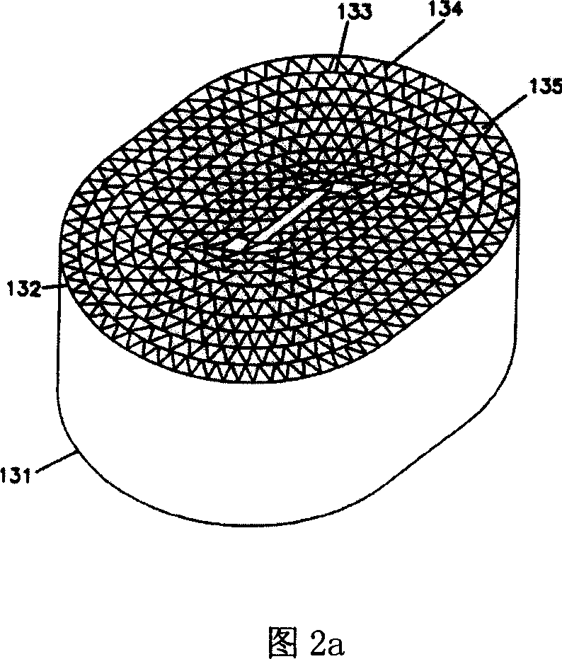
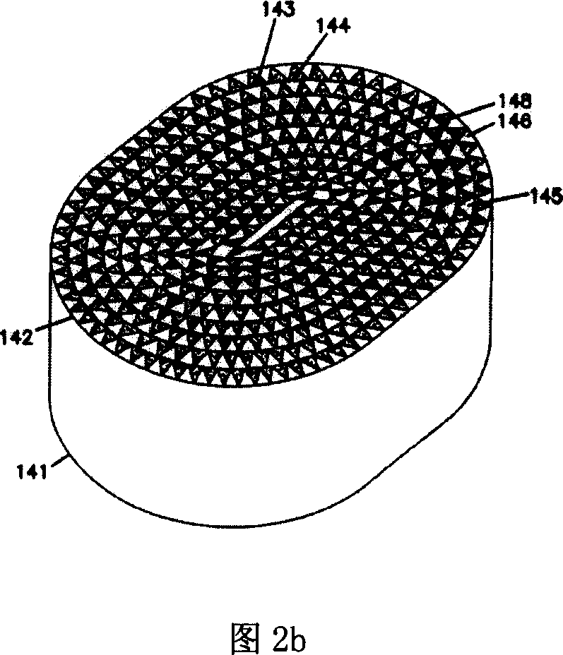
The difference between Figure 2a and Figure 2b is that the air flow channels are different. In a, the air can directly flow from the side 131 through the channel 135 to the side 132. In b, adhesives are used to alternately bond the two ends 141 and 142 of the channel 145 so that the air can flow freely. The process must pass through the wall 133 or 134, thus improving the purification effect, but resulting in increased air turbulence, which is not conducive to gas transmission
The device uses chemical components to remove impurity gases in the air, which can improve the purification efficiency compared with purely using activated carbon. However, although the method of loading adsorption materials can reduce air transmission resistance, it still loses compared to the method of penetrating adsorption of high-porosity materials. partial purification efficiency
In addition, the process of bonding channels makes the purifier manufacturing process more complicated
[0007] Since the purifier adopts the principle of adsorption to remove impurity gases, it is inevitable to replace the adsorbent during use, but unfortunately, there is currently no product that can easily replace the adsorbent alone

Method used


Image

  • Engine air cleaner
  • Engine air cleaner
  • Engine air cleaner

Examples


Embodiment Construction

[0045] Fig. 3 shows the embodiment of the engine air purifier of the present invention, and it comprises conical air intake channel 1, hydrophobic polymer film 4, adsorption layer housing 6, the adsorption layer that is located in the adsorption layer housing 6, stainless steel filter screen 7. Conical air outlet channel 9, wherein the adsorption layer includes a plurality of layered monolithic adsorbents 11 arranged at intervals, air flow channels 12, and a plurality of air flow channels arranged alternately in the layered structure The wedge-shaped baffles 15 between the integral adsorbents 11 and the net-shaped adsorption layer support frame 16 fixedly connected with the wedge-shaped baffles 15 . The tapered air inlet channel 1 and the tapered air outlet channel 9 are respectively fixed at both ends of the adsorption layer housing 6 . The hydrophobic polymer film 4 is fixed between the conical air inlet channel 1 and the adsorption layer housing 6 , and the stainless steel ...


PUM

PropertyMeasurementUnit
angleaaaaaaaaaa

Abstract

The invention provides an engine air cleaner, which comprises the following parts: an adsorbed layer casing, an adsorbed layer equipped in the adsorbed layer casing, wherein the absorbed layer includes a plurality of air flow channels, an integral absorbed agent arranged alternatively with the air flow channel, a plurality of wedge-shaped baffle plates arranged on the air flow channel. The improvement program still comprises the following parts: a pyramid air-in channel, a hydrophobicity polymeric film, a non-corrodible steel filter gauze, a pyramid air-out channel, a supporting frame or the like, wherein the absorbed layer is manufactured by the renewable, conveniently unpacking and changing and integral absorbed agent and is fixed in the supporting frame of the absorbed layer interior, the casing of the absorbed layer with the wedge-shaped baffle plate optimizes the flow characteristic of the air in order to reduce the resistance and noise of the air, the supporting frame, the cleaner casing, the wedge-shaped baffle plate, the integral absorbed agent seals separately with collar seal in order to avoid the air short circuit. The invention removes the gaseous impurity and the particulate effectively in the condition of reducing the air resistance as possible as we can.

Description

technical field [0001] The invention relates to an engine air cleaning device. Background technique [0002] Due to the increasingly prominent problems of energy shortage and environmental pollution, the development of clean energy vehicles is receiving more and more attention. Among them, fuel cell vehicles use environmentally friendly and efficient proton exchange membrane fuel cells (PEMFC) as a power source, which can effectively solve traditional problems. The dependence of automobiles on fossil energy and the problem of environmental pollution have become the focus of government support in developed countries and the development direction of well-known automobile companies. [0003] At present, fuel cell vehicles use air as the oxidant, but studies have shown that particulate matter in the air and impurity gases such as CO, C m h n , NO x , SO 2 and H 2 S, etc. will reduce the performance of the fuel cell and affect the life of the fuel cell. It can be foreseen t...

Claims


Application Information

Patent Timeline
Patent Type & Authority Applications(China)
IPC IPC(8): H01M8/04H01M8/06H01M8/00B01D53/02B01D50/00H01M8/0662
CPCY02E60/50Y02P70/50
Inventor 马建新周伟马晓伟杨代军张存满潘相敏
Owner TONGJI UNIV
Why Eureka
Try Eureka