Method of reinforcing a bridge

A technology for bridges and reinforcement plates, which is applied in bridges, bridge maintenance, bridge reinforcement, etc., can solve problems such as increasing costs, and achieve the effect of increasing load capacity and minimizing damage

Inactive Publication Date: 2007-12-19
INTELLIGENT ENG BAHAMAS
2 Cites 7 Cited by

AI-Extracted Technical Summary

Problems solved by technology

Rerouting also ...

Method used

[0047] In a fifth embodiment of the present invention, repairs are performed on the underside of the prefabricated steel plate of the viaduct to enhance fatigue resistance and prolong the service life of the structure. The repair shown in Figure 9 is identical in shape and structure to the existing structure and does not degrade original performance.
[0049] A combination of flexible, closed-cell foam-like material and caulking is used to seal the ends of the cavity. The cavity is then injected from below, first through the central region and then to either end, to ensure complete filling with core material 505 . This method of repair not only reduces the stress range in existing prefabricated steel panels (at or a...

Abstract

A method of repairing, reinforcing or reinstating a bridge, comprising fixing a reinforcing plate in a spaced relationship with an existing plate or girder, especially on the underside of the bridge structure, to form a closed cavity, and injecting plastics or polymer material into said cavity in liquid form, whereby said plastics or polymer material sets or cures so as to bond to said reinforcing and existing plates with sufficient strength to transfer shear forces therebetween.

Application Domain

Technology Topic

Image

  • Method of reinforcing a bridge
  • Method of reinforcing a bridge
  • Method of reinforcing a bridge

Examples

  • Experimental program(1)

Example Embodiment

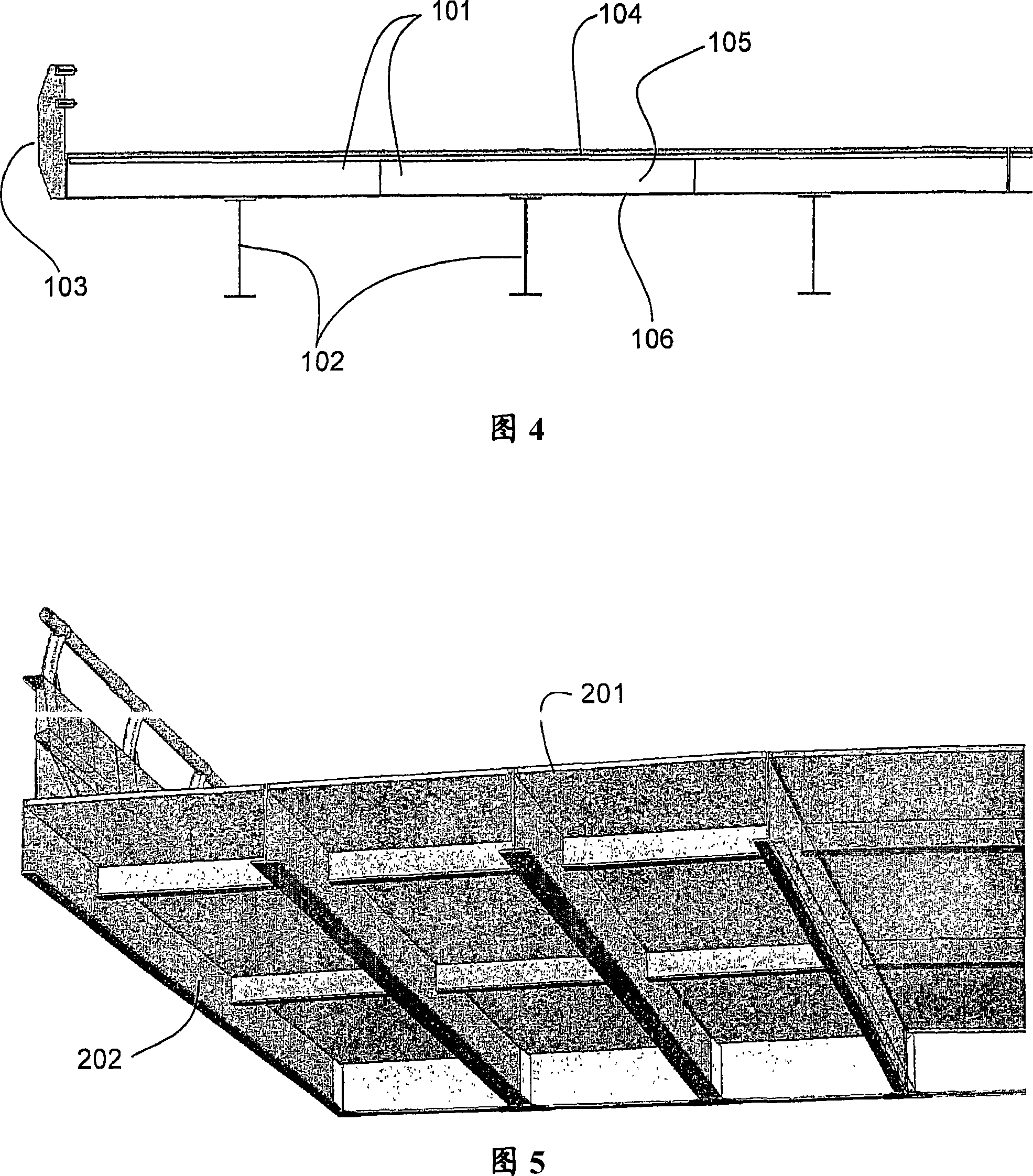
[0035]According to a first embodiment of the present invention, an existing concrete deck composite steel girder bridge is repaired by replacing the concrete deck with a prefabricated SPS deck panel 101 as shown in FIG. 4 . Subsequently, the SPS deck panels are composited with the existing steel girders 102 by bolting or welding between the panels 101 . Replacement SPS panels 101 are continuously formed by welding them together at adjoining edges. Existing or new steel parapets 103 can be bolted to the SPS deck deck.
[0036] Each SPS panel 101 includes outer metal panels 104, 106 bonded together by an intermediate or core layer 105 of plastic or polymeric material. The outer metal panel may be a steel plate with a thickness in the range of 2-20 mm according to specific application requirements. For plastic or polymeric materials, it is preferred to use compressed (ie non-foamed) thermosetting materials such as polyurethane elastomers. The core layer 105 may have a thickness in the range of 15-200 mm and be bonded to the face sheets 104, 106 with sufficient strength and with sufficient mechanical properties to transfer the shear desired in the application between the reinforcement and the existing structure force. The bonding strength should be greater than 3MPa, preferably greater than 6MPa, and especially when exposed to high temperature, the modulus of elasticity of the core material should be greater than 200MPa, preferably greater than 250MPa. Due to the effect of the core layer, the reinforced structure has the strength and load capacity only possessed by the reinforced steel plate with substantially greater plate thickness and greater additional rigidity. Of course, the replacement panel 101 does not have to be flat, but no matter what shape it adopts, it should be suitable for the existing structure.
[0037] The use of prefabricated SPS deck panels provides ease of deck replacement which translates into shorter construction periods which can accommodate limited closures. Prefabricated SPS deck panels offer the further advantage of factory quality control and limited quantity of field assembly, which is well known and widely applied, thus providing the deck structure with a service life similar to that of the steel superstructure.
[0038] In a second embodiment of the invention, as shown in FIG. 5 , the superstructure is completely replaced by SPS panels 201 with integral beams 202 . The SPS panel 201 is substantially the same as the panel 101 in the first embodiment, but the longitudinal and/or transverse beams 202 are integrated with the panel during off-site assembly. The web of the beam may form the side wall part of the cavity into which the core material is injected, while one or both face sheets may serve as the edge of the beam. As in the first embodiment, prefabricated SPS deck panels provide ease of deck replacement, factory quality control and limited field assembly quantities, with subsequent advantages.
[0039] In addition, the first and second embodiments of the present invention provide bridge decks with equal or greater strength and stiffness than the original reinforced concrete deck while reducing weight by up to 75%. Deck weight reductions of this magnitude allow either increased load capacity or the number of traffic lanes without the need for embankment reinforcement or the addition of additional girders.
[0040] As shown in FIG. 6 , in a third embodiment of the present invention, the existing structure of a bridge comprising a load deck 20 and a stiffening trough (stiffening trough) 21 is passed through an additional reinforcing plate 33 spanning between the bottoms of the stiffening trough 21 1 while being repaired or reinforced. Depending on the requirements of a particular application, the reinforcing plate 331 may be a steel plate having a thickness in the range of 2 to 20 mm. To bond the reinforcing plate 331 to the existing structure, a core layer 332 of plastic or polymeric material, preferably a compression thermosetting material such as polyurethane elastomer, may be employed. The core may have a thickness in the range of 15-200mm. The core 332 is bonded to the reinforcing plate 331 and the existing structure 20, 21 with sufficient strength and has sufficient mechanical properties to transmit the shear forces expected in the application between the reinforcing member and the existing structure. The bonding strength should be greater than 3MPa, preferably greater than 6MPa, and especially when exposed to high temperature, the modulus of elasticity of the core material should be greater than 200MPa, preferably greater than 250MPa. Due to the effect of the core layer, the reinforced structure has the strength and load capacity only possessed by the reinforced steel plate with substantially greater plate thickness and greater additional rigidity. Of course, the reinforcing plate does not have to be flat, but whatever shape is used must fit the existing structure.
[0041] In order to reduce the volume of core material required to bond the reinforcement to the existing structure, lightweight moldings or inserts 333 are provided in the spaces between the rigid slots 21 . The profile 333 preferably has a cross-sectional shape matching that of the spaces between the grooves, but is sized such that the thickness of the core material layer is in the range of around 15-200mm. The profiled part is preferably an elongated hollow body of suitable section, but can also be made of a lightweight material, such as foam. Each insert can also consist of multiple extensions of standard profile to avoid the need to manufacture specific moldings for each bridge.
[0042] As shown more clearly in FIG. 7 , which is an enlarged view of the maintenance bridge, each profile 333 preferably consists of two parts 334 that fit into sleeves 335 so that the length of the profile can be adjusted by sliding the parts 334 into or Set out 335 to adjust. End caps 336 close off both ends of the molding. This setup is suitable for bridges where the profile and spacing of the rigid slots are constant, but the spacing between the transverse beams can be varied.
[0043] Especially when hollow, the molded part can be adapted to any application, for example, water or air pipes, power or communication cables that can be attached to the underside of bridges. If suitable access points and through-holes are provided in the transverse beams, the hollow formed part can also serve as a relay for additional applications at a later date.
[0044] To effectuate repairs, the lower surfaces of all slots 21 and exposed panels of the bridge deck 20 are first grit blasted to provide a clean surface to which the core material can adhere. The form 333 is then fixed in place, for example by spot welding, with suitable spacers. Once complete, landing bars are welded in place on the edges of the gusset so that the gusset can be welded in place. The cavity defined by the reinforcement plate and the existing structure is sealed, with filling and venting holes as required. The core material is then injected and allowed to cure to form a strong bond between the stiffener and the existing structure. To finish, the fill port and vent hole may be sealed and ground flush prior to any desired surface treatment, eg, painting to prevent corrosion or for aesthetic reasons.
[0045] The same bridge can be repaired by adding a covering on the top surface, as shown in FIG. 8 in a fourth embodiment of the invention. In this embodiment, a reinforcing plate 401 is fixed over the existing plate 20 to form a cavity. This cavity is then filled by injecting a plastic or polymeric material 402 which, when set, will bond the reinforcing plate 401 to the existing plate 20 with sufficient strength to transmit the shear forces expected in the application . In this respect, the fourth embodiment is the same as the other embodiments of the present invention, and the reinforcing plate and core material are as described above. When the core layer is fully cured, an asphalt pavement surface 403 is laid on top of the reinforcement boards.
[0046] To secure the reinforcement plate 401 in place prior to injecting the core, a welded or glued perimeter bar is used to define the cavity to be filled. Spacers and lightweight moldings or inserts may also be employed, as in other embodiments of the invention.
[0047] In a fifth embodiment of the present invention, repairs are performed on the underside of the prefabricated steel plate of the viaduct to enhance fatigue resistance and prolong the service life of the structure. The repair shown in Figure 9 is identical in shape and structure to the existing structure and does not degrade original performance.
[0048] To be repaired from below without affecting the rail service, two prefabricated panels 501, 502, shape-matched to the existing structure, are bolted to the web of transverse beams of the existing structure and secured with one-sided rivets ( One-side rivets) are riveted to each other, as shown in Figure 10, forming a lap joint 503 in the middle of the length of the panels extending across the bridge. Lap joints provide simple connection details that allow for dimensional variations along the length of the bridge. Then, the drain 504 is reconstructed as in FIG. 11 .
[0049] A combination of flexible, closed-cell foam-like material and caulking is used to seal the ends of the cavity. The cavity is then injected from below, first through the central region and then to either end, to ensure complete filling with core material 505 . This method of repair not only reduces the stress range in existing prefabricated steel panels (at or adjacent to the leading edge, above the flanged ends of the transverse beams where the cantilevered slab part passes), thereby enhancing fatigue resistance, A visco-elastic layer is also provided to absorb structure noise and is of added benefit to city centers with elevated rail systems like this one.
[0050] The sixth embodiment of the present invention is a modification of the existing structure. As shown in FIGS. Structural noise associated with vibrations caused by traffic (road or rail) carried by a bridge. Additional effects of the invention are structural reinforcement, increased shear resistance and fatigue resistance due to weld groups connecting the rigid members to the web.
[0051] In the fifth and sixth embodiments, the materials and dimensions of the reinforcing plate and the core may be the same as in the previously described embodiments.
[0052] It should be understood that the above description is not limiting and that other modifications and changes are possible within the scope of the invention as defined by the appended claims.

PUM

PropertyMeasurementUnit
Thickness0.5 ~ 20.0mm
tensileMPa
Particle sizePa
strength10

Description & Claims & Application Information

We can also present the details of the Description, Claims and Application information to help users get a comprehensive understanding of the technical details of the patent, such as background art, summary of invention, brief description of drawings, description of embodiments, and other original content. On the other hand, users can also determine the specific scope of protection of the technology through the list of claims; as well as understand the changes in the life cycle of the technology with the presentation of the patent timeline. Login to view more.

Similar technology patents

Gas turbine inlet air temperature control system

PendingCN114635797AImprove load capacityIncrease intake air temperatureGas turbine plantsJet propulsion plantsWater circulationEngineering
Owner:HUANENG BEIJING CO GENERATION

Reinforced bed frame

ActiveUS20200146460A1Improve load capacityImprove efficiencyBedstandsEngineeringStructural engineering
Owner:NEW TEC INTEGRATION (XIAMEN) CO LTD

Classification and recommendation of technical efficacy words

  • Improve load capacity
  • Damage minimization

Reinforced bed frame

ActiveUS20200146460A1Improve load capacityImprove efficiencyBedstandsEngineeringStructural engineering
Owner:NEW TEC INTEGRATION (XIAMEN) CO LTD

Container lid structure

InactiveCN107954071ADamage minimizationImprove the effect of initial washingClosure with auxillary devicesRemovable lids/coversEngineeringMechanical engineering
Owner:株式会社碧珍

Water drainage pump

InactiveCN1884838ADamage minimizationNoise minimizationPump componentsOther washing machinesImpellerEngineering
Owner:LG ELECTRONICS (TIANJIN) APPLIANCES CO LTD
Why Eureka
Try Eureka