Fluid pressure circuit, energy recovery device, and fluid pressure recovery circuit for working machine

A fluid pressure and energy regeneration technology, applied in the direction of fluid pressure actuating device, fluid pressure actuating system components, mechanical equipment, etc., can solve the problem of reduced operating speed, inability to set up mutual complementary working fluid support circuits, and inability of boom cylinders to work. Stability and other issues, to achieve the effect of suppressing sudden load fluctuations, realizing stable operation, and suppressing load fluctuations

Inactive Publication Date: 2007-12-19
SHIN CATERPILLAR MITSUBISHI LTD CORP
View PDF1 Cites 37 Cited by
  • Summary
  • Abstract
  • Description
  • Claims
  • Application Information

AI Technical Summary

Problems solved by technology

[0005] The driving device of the above-mentioned work machine is provided with a pump/motor in the closed circuit of the boom cylinder, so when the pump/motor functions as a fluid pressure motor, it starts up rapidly due to the return fluid from the boom cylinder, and due to The disappearance of the return fluid causes a sudden stop, which causes a shock, and the pump/motor becomes a load on the boom cylinder, and the load fluctuates depending on whether the pump/motor is in a stopped state or an operating state, so the operation of the boom cylinder is unstable.
[0006] Also, devices combining the pump/motor and motor/generator described are limited to closed circuits and cannot be adapted for open circuits where return fluid exhausted from a fluid pressure actuat

Method used


Image

  • Fluid pressure circuit, energy recovery device, and fluid pressure recovery circuit for working machine
  • Fluid pressure circuit, energy recovery device, and fluid pressure recovery circuit for working machine
  • Fluid pressure circuit, energy recovery device, and fluid pressure recovery circuit for working machine

Examples


Example Embodiment

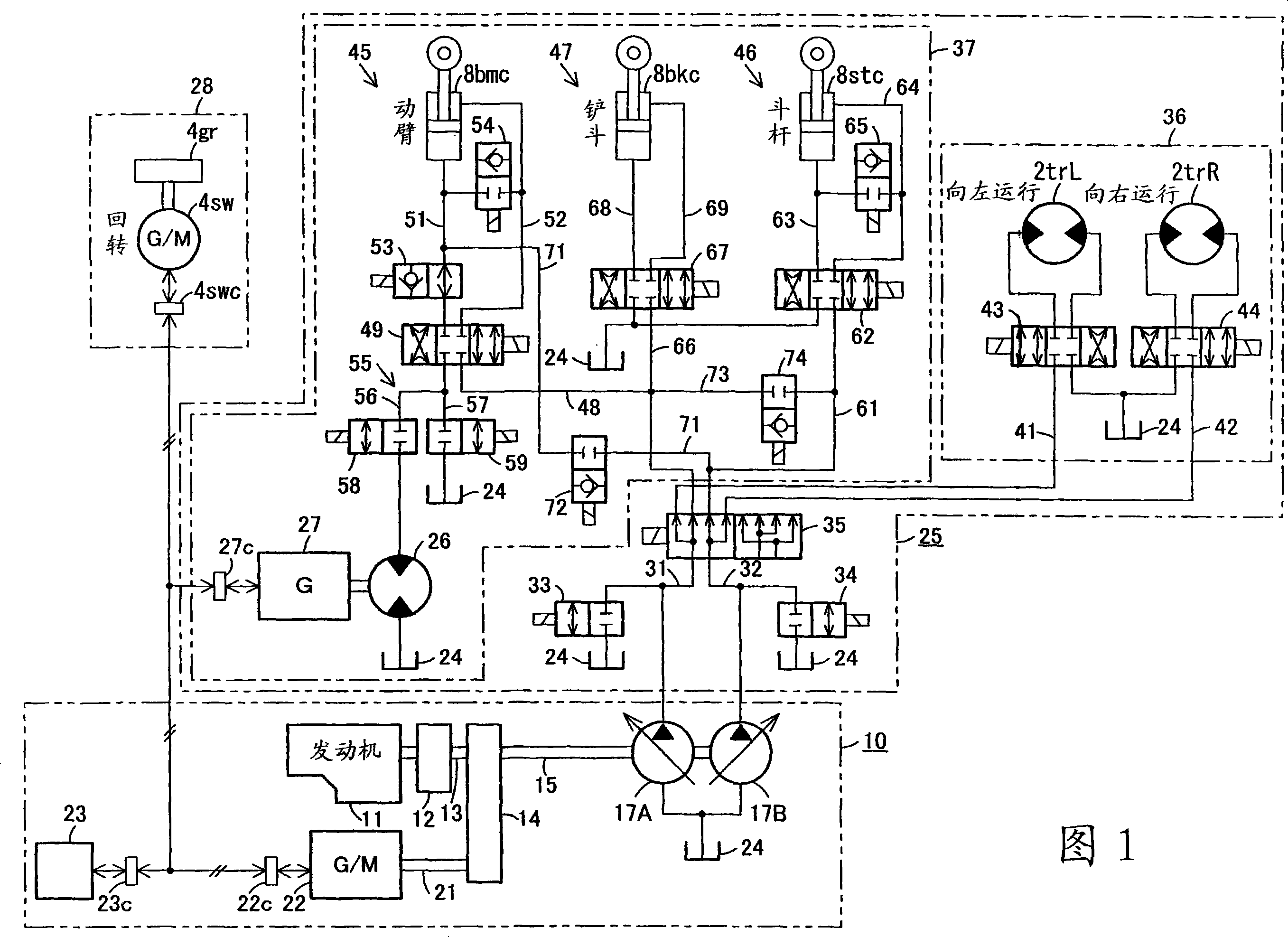
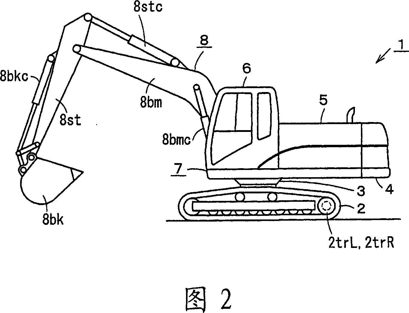
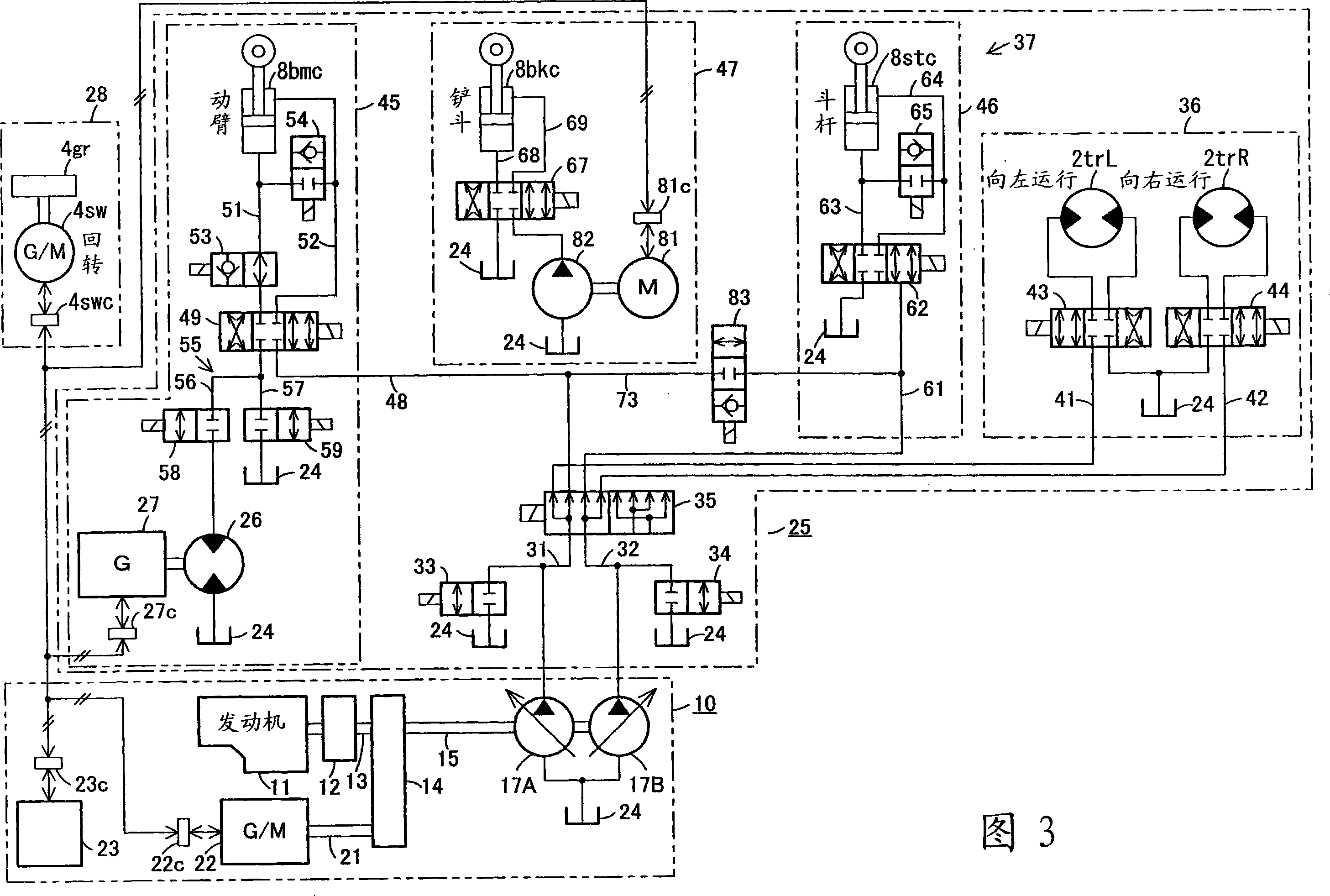
[0036] Hereinafter, referring to the first embodiment shown in FIGS. 1 and 2 and the second embodiment shown in FIG. 3, the third embodiment shown in FIG. 4, the fourth embodiment shown in FIG. 5, and the fourth embodiment shown in FIG. The fifth embodiment of the fifth embodiment, the sixth embodiment shown in FIG. 7 and the modified examples of the hybrid drive device shown in FIG. 8 will specifically describe the present invention.

[0037] First, the first embodiment shown in FIGS. 1 and 2 will be described.

[0038] As shown in Figure 2, the working machine 1 is a hydraulic excavator. The lower running body 2 is provided with an upper rotating body 4 rotatably through a rotating bearing 3, and an engine and fluid pressure are installed on the upper rotating body 4 A power unit 5 such as a pump, a cab 6 that protects an operator, and the like, thereby forming a body 7. The lower running body 2 has running motors 2trL and 2trR for driving the left and right crawlers, respective...


PUM


Abstract

A fluid pressure circuit where energy possessed by return fluid from a fluid pressure actuator can be smoothly absorbed by an energy recovery motor and where stable operation of the fluid pressure actuator can be obtained. A return fluid path (55) to which return fluid discharged from a boom cylinder (8bmc) is branched is provided on the tank path side of a solenoid valve (49) of a boom control circuit (45). In one return path (56) and the other return path (57) of the return path (55) are provided proportional flow control valves (58, 59) for controlling flow ratios branched to the return paths (56, 57). The proportional flow control valves (58, 59) are composed of one solenoid valve (58) for flow control provided in the one return path (56) having the energy recovery motor (26) and of the other solenoid valve (59) for flow control provided in the other return path (57) branched off on the upstream side of the one solenoid valve (58).

Description

technical field [0001] The invention relates to a fluid pressure circuit with an energy regeneration motor, an energy regeneration device, a fluid pressure circuit of a working machine with a boom auxiliary pump. Background technique [0002] A driving device of a work machine such as a hydraulic excavator includes a generator driven by an engine, and a battery storing electric power generated by the generator. The pump or the pump / motor is driven by an electric motor or an electric / generator operated by electric power supplied from at least one of these generators and accumulators. For example, the drive circuit of the boom cylinder is equipped with a bidirectional output pump / motor that has both the pump function of providing working fluid and the function of a fluid pressure motor that receives the supply of working fluid in a closed circuit, and also has a motor / generator. It has both a motor function for driving a pump / motor driven by electric power supplied from a gen...

Claims


Application Information

Patent Timeline
IPC IPC(8): F15B21/14F15B11/16E02F9/22
CPCE02F9/2075E02F9/2217E02F9/2239
Inventor 戸泽祥二备中円古田秀人
Owner SHIN CATERPILLAR MITSUBISHI LTD CORP
Why Eureka
Try Eureka