Electron bombardment welding turbine shaft, and producing technique

A technology of vacuum electron beam welding and production process, which is applied in the direction of electron beam welding equipment, manufacturing tools, welding equipment, etc., and can solve problems such as inconsistent centerline speed, uneven mechanical strength, and large processing allowance

Inactive Publication Date: 2007-12-26
刘天成
View PDF0 Cites 10 Cited by
  • Summary
  • Abstract
  • Description
  • Claims
  • Application Information

AI Technical Summary

Problems solved by technology

In this friction welding method, the utilization rate of the turbine shaft material is only about 35%. During the friction rotation welding process, the center line speed of the welding end face of the turbine shaft is inconsistent, the melting temperature is uneven, the mechanical stre

Method used


Image

  • Electron bombardment welding turbine shaft, and producing technique
  • Electron bombardment welding turbine shaft, and producing technique
  • Electron bombardment welding turbine shaft, and producing technique

Examples


Embodiment 1

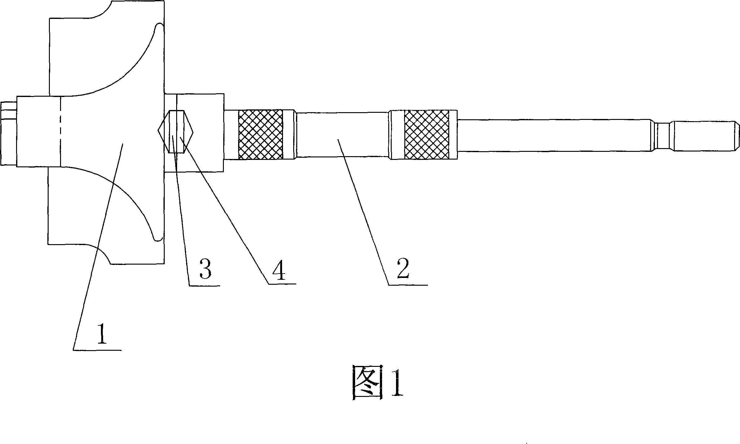
[0021] As shown in Figure 1, the vacuum electron beam welding turbine shaft technical scheme of the present invention: the center of the smooth turbine 1 welding end surface is provided with a hole 3 with a depth of 1-2MM, and the center of the corresponding turbine shaft 2 welding end surface is also provided correspondingly. There is a hole 4 with a depth of 1-2MM. Use professional tools to ensure the concentricity of the two, so that the welding end faces are kept parallel, and the welding end faces of the turbine and the welding end faces of the turbine shaft are fixedly connected by vacuum electron beam welding.

[0022] The vacuum electron beam welding turbine shaft production process of the present invention is as follows:

[0023] Machining the welding end face of the turbine is carried out by machining to make the machined surface of the turbine smooth; a hole with a depth of 1-2 mm is set in the center of the welding end face of the turbine according to different whee...


PUM


Abstract

This invention relates to a technology for welding turbine shafts with vacuum electronic beams, in which a hole of 1-2mm deep is set at the center of a turbine welding end face and a hole of 1-2mm deep is set correspondingly at the center of a turbine shaft end face and concentricity of the two is kept by a special tool to keep the welding end faces parallel and connected fixedly by vacuum electronic beam welding. The method includes: processing a turbine welding end face and setting a hole of 1-2mm deep at the center, processing a shaft welding end face and setting a hole of 1-2mm deep correspondingly at the center to fixedly connect them by vacuum electronic beam welding. Advantages: tensile strength of the welding is greater than original material, high usability of materials, mechanical process stress is small and shaft stability is good.

Description

technical field [0001] The invention relates to a vacuum electron beam welding technology, in particular to the technical field of a vacuum electron beam welding turbine shaft and its production technology. Background technique [0002] At present, the demand for turbochargers in the world is increasing at a rate of 10%, while that in my country is increasing at a rate of 30%. It can be seen that the market demand for turbochargers is huge and the prospect is broad. The assembly and fixation of turbine and turbine shaft is one of the key technologies in the production of turbocharger, which plays an important role in improving the product quality and reducing product cost of turbocharger. Friction welding is now commonly used to fix the turbine to the end of the turbine shaft. In this friction welding method, the utilization rate of the turbine shaft material is only about 35%. During the friction rotation welding process, the center line speed of the welding end face of th...

Claims


Application Information

Patent Timeline
IPC IPC(8): F01D5/02F01D5/30B23K15/06
Inventor 刘天成
Owner 刘天成
Why Eureka
Try Eureka