Nozzle of steam turbine with structure of groove face by using electron beam bonding
An electron beam welding and welding groove technology is applied in the field of welding structure of steam turbine nozzles, which can solve the problems of affecting the efficiency of steam turbines, many related parts, and difficult assembly, and achieves simplification of structure, reduction in volume, and difficulty in protection. Effect
- Summary
- Abstract
- Description
- Claims
- Application Information
AI Technical Summary
Problems solved by technology
Method used
Image
Examples
specific Embodiment approach 1
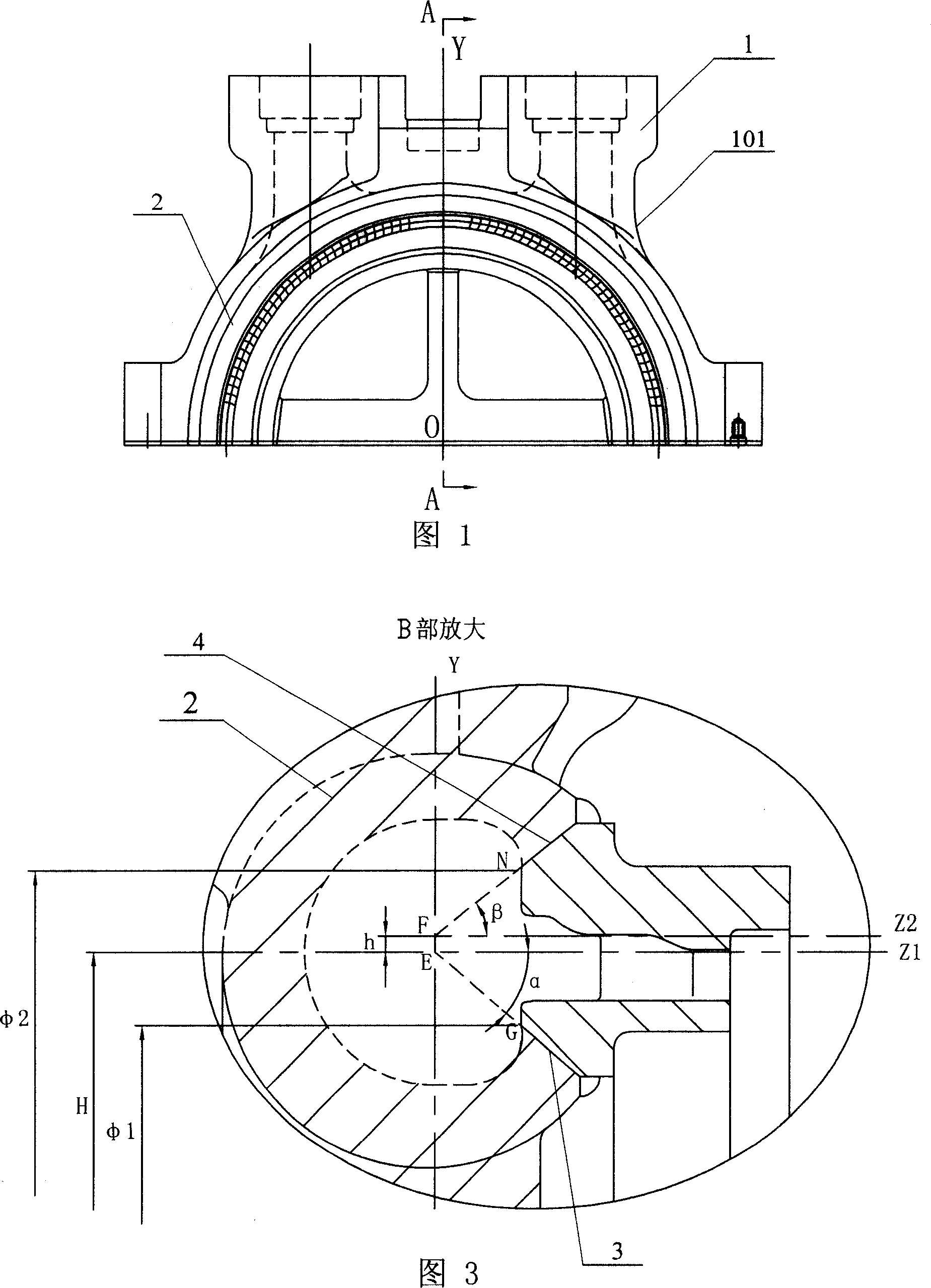
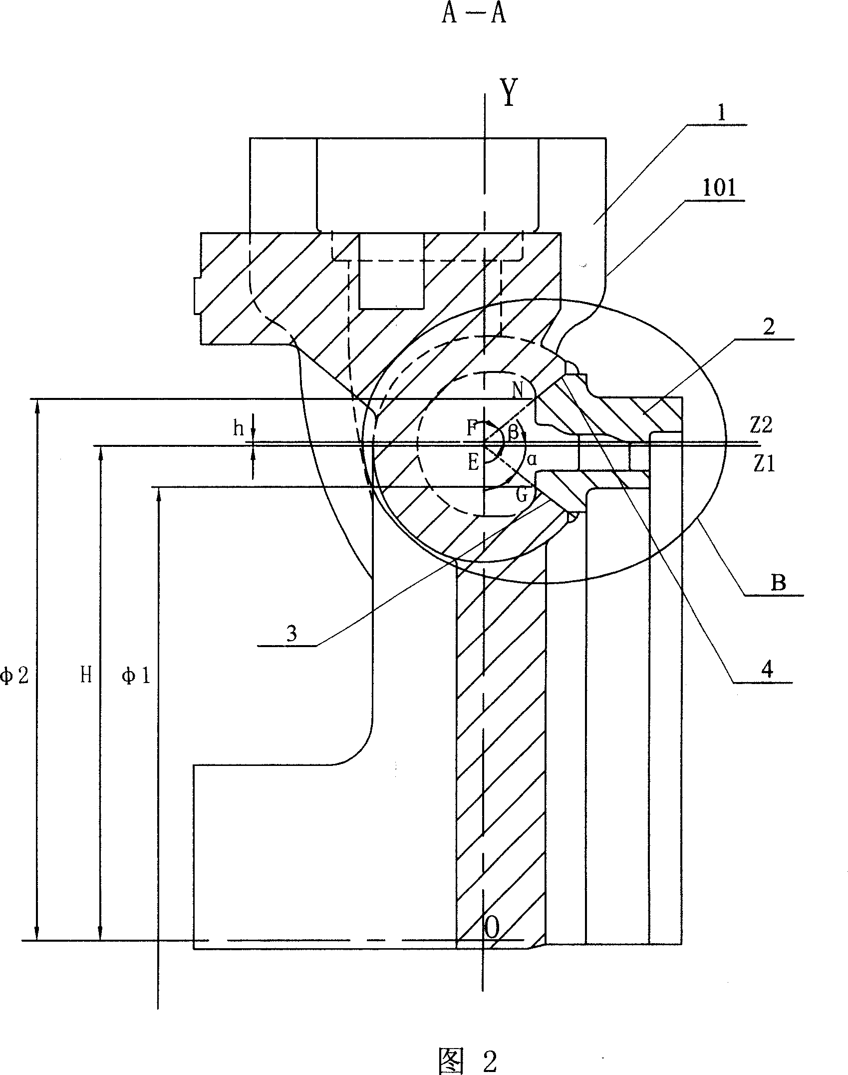
[0008] Embodiment 1: This embodiment will be described with reference to FIGS. 1 to 3 . The nozzle 101 of this embodiment is composed of a nozzle chamber 1 and a nozzle group 2 ; the extension of the lower welding groove surface 3 between the nozzle chamber 1 and the nozzle group 2 The line intersects the point E of the Y-direction central axis of the nozzle 101, the distance H between the point E and the center point 0 of the nozzle 101 is 1100mm, and the clip between the lower welding groove surface 3 and the Z1 direction line passing through the point E The angle α is 40°, the extension line of the upper welding groove surface 4 between the nozzle chamber 1 and the nozzle group 2 intersects the point F of the Y-direction central axis of the nozzle 101, the point F is located above the point E, and the point F to The distance h from point E is 5mm, and the angle β between the upper welding groove surface 4 and the Z2 direction line passing through point F is 40°.
specific Embodiment approach 2
[0009] Embodiment 2: This embodiment will be described with reference to FIG. 2 and FIG. 3 . The inner point G of the lower welding groove surface 3 of this embodiment intersects with the center point O of the nozzle 101 as the center of the circle and the diameter Φ1 is 1014mm. The above technical parameters are used to facilitate the welding positioning between the groove surface of the nozzle group 2 and the groove surface of the nozzle 1 . Other components and connection relationships are the same as in the first embodiment.
specific Embodiment approach 3
[0010] Embodiment 3: This embodiment will be described with reference to FIG. 2 and FIG. 3 . The inner end point N of the upper welding groove surface 4 of this embodiment intersects on a circle with the center point O of the nozzle 101 as the center and a diameter of Φ2 of 1196 mm. The above technical parameters are used to facilitate the welding positioning between the groove surface of the nozzle group 2 and the groove surface of the nozzle 1 . Other components and connection relationships are the same as in the first embodiment.
[0011] During welding, the nozzle 101 is placed on the variable turntable by using the complementary relationship in geometry. After adjustment, the variable turntable is deflected by 50°, and the horizontal welding of the outer arc is carried out. After the external arc is welded, the inner arc is carried out. For welding, the material of the nozzle is 1Cr9MoVNiN, the thickness of the nozzle is 45mm, and the welding vacuum degree is 7.4×10 -4 m...
PUM
 Abstract
Description
Claims
Application Information
 - R&D
- Intellectual Property
- Life Sciences
- Materials
- Tech Scout
- Unparalleled Data Quality
- Higher Quality Content
- 60% Fewer Hallucinations
Browse by: Latest US Patents, China's latest patents, Technical Efficacy Thesaurus, Application Domain, Technology Topic, Popular Technical Reports.
© 2025 PatSnap. All rights reserved.Legal|Privacy policy|Modern Slavery Act Transparency Statement|Sitemap|About US| Contact US: help@patsnap.com


