Motor control unit

A control device and motor technology, applied in the direction of motor generator control, AC motor control, electric controller, etc., can solve problems such as difficult positioning, and achieve the effect of improving position resolution

Inactive Publication Date: 2008-01-02
KK TOSHIBA
View PDF1 Cites 15 Cited by
  • Summary
  • Abstract
  • Description
  • Claims
  • Application Information

AI Technical Summary

Problems solved by technology

As a result, no matter how much the resolution of position detection devices such as encoders is improved, it is diffic...

Method used


Image

  • Motor control unit
  • Motor control unit
  • Motor control unit

Examples


Embodiment 1

[0024] Hereinafter, Embodiment 1 of the present invention will be described with reference to FIGS. 1 to 3 .

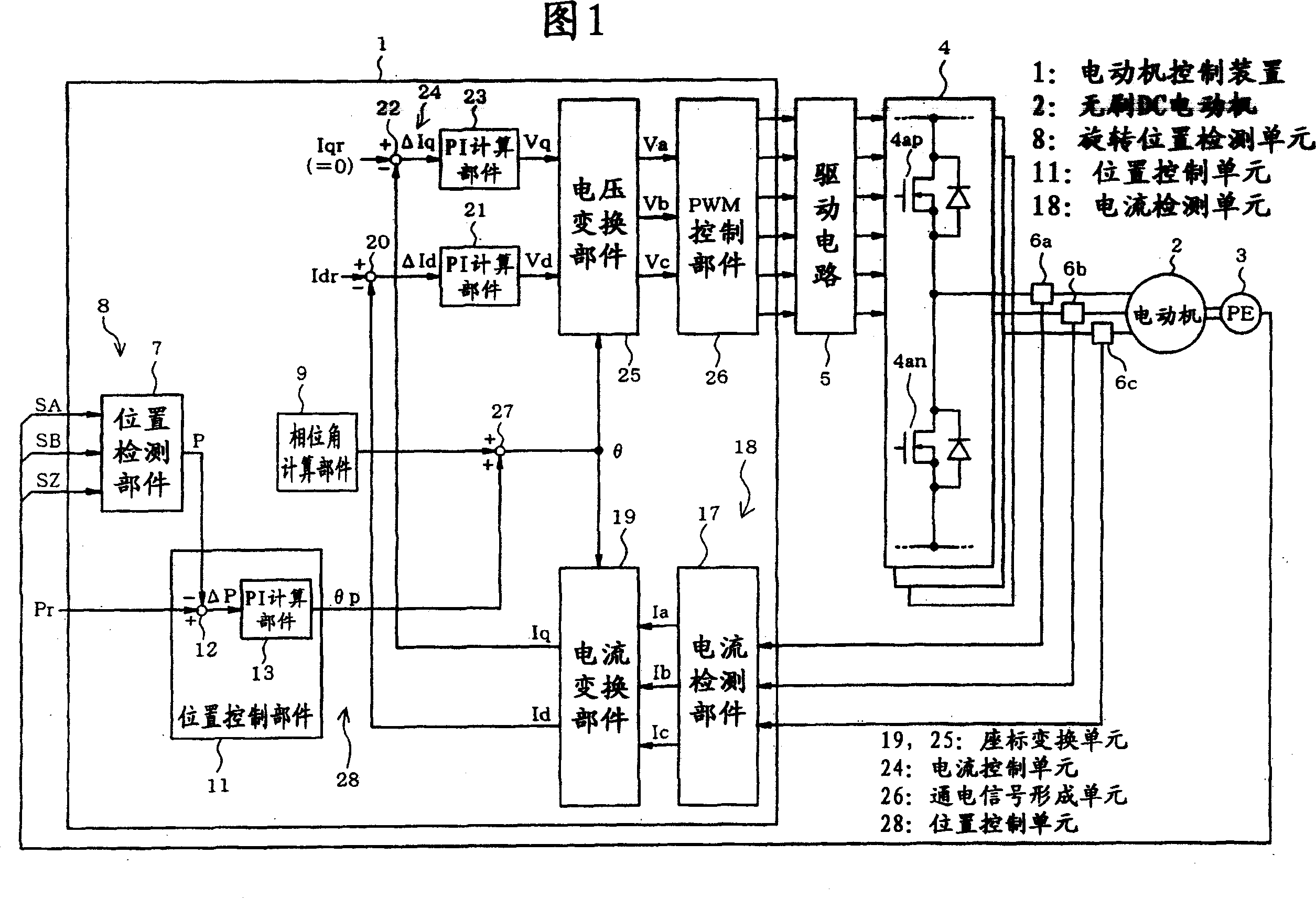
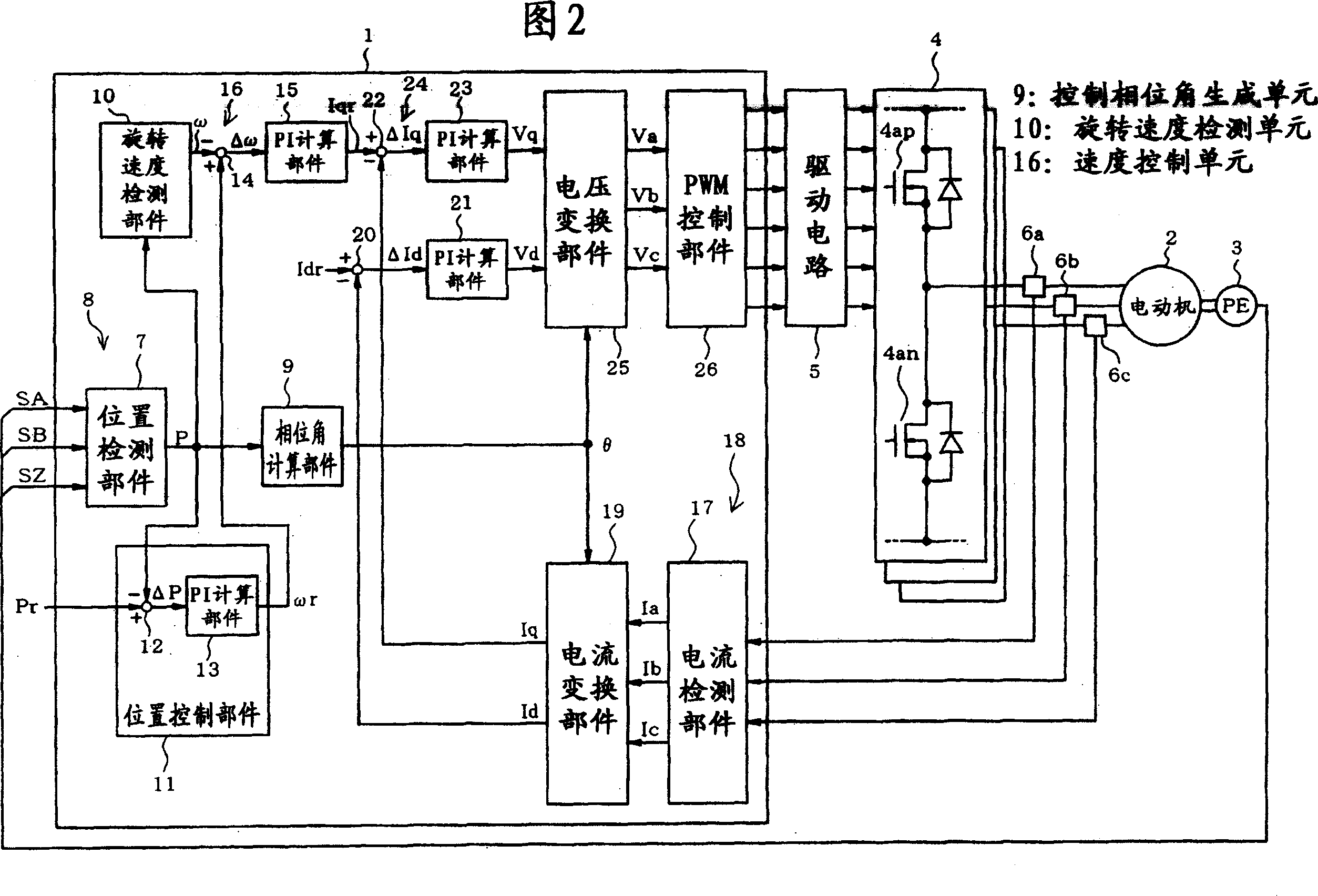
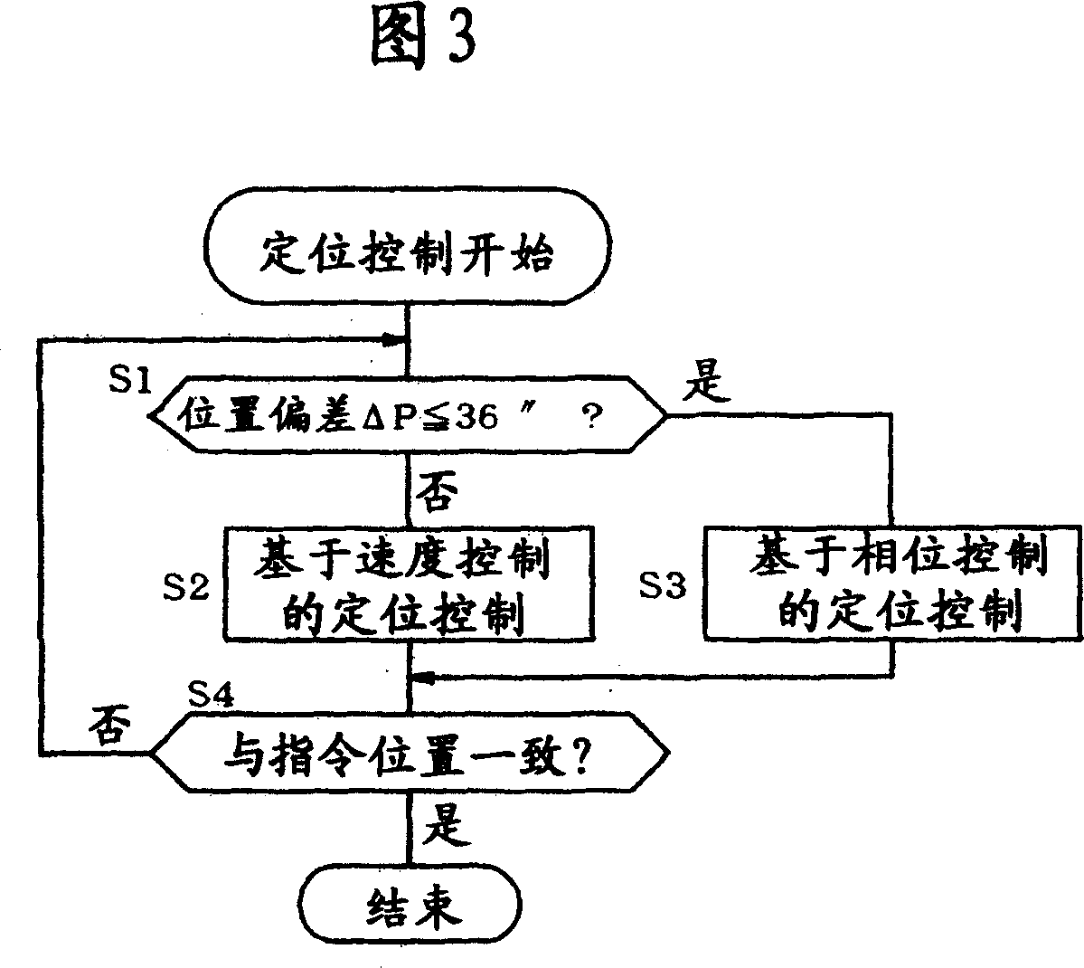
[0025] Figure 1 and Figure 2 show the structure of the motor control system. When the position deviation ΔP is large, the motor control device 1 adopts the same structure as the prior art shown in FIG. The deviation Δω correspondingly obtains the speed feedback loop of the command current as a secondary loop (hereinafter referred to as positioning control based on speed control). In this regard, if the position deviation ΔP is less than or equal to the specified value, as shown in Fig. 1, the following position feedback loop (hereinafter referred to as positioning control based on phase control) is adopted, that is, when the speed feedback loop is disabled and the command current becomes Based on a constant value, the phase angle θ (hereinafter referred to as phase angle θ) is controlled in accordance with the positional deviation ΔP.

[0026] First, the control str...

Embodiment 2

[0056] Next, Embodiment 2 of the present invention will be described with reference to FIG. 4 and FIG. 5 .

[0057] Fig. 4 and Fig. 5 show the structure of the motor control system, and the same reference numerals are assigned to the same parts as Fig. 1 and Fig. 2 . The motor control device 29 is different from the first embodiment in that it directly controls the voltage without having a current control loop.

[0058] When the position deviation ΔP is large, the motor control device 29 adopts a position feedback loop to obtain the command rotational speed ωr corresponding to the position deviation ΔP as shown in FIG. Velocity feedback loop for Vq (positioning control based on velocity control). The PI calculation section 30 performs PI calculation on the speed deviation Δω to generate the command q-axis voltage Vq, and thus constitutes the speed control unit 31 together with the subtractor 14 . In addition, the d-axis voltage Vd is a constant value.

[0059] If the positi...

Embodiment 3

[0062] Next, Embodiment 3 of the present invention will be described with reference to FIGS. 6 to 9 .

[0063] FIG. 6 shows the configuration of the motor control system, and the same parts as those in FIG. 1 are assigned the same reference numerals. When the position deviation ΔP is large, the motor control device 33 executes the positioning control based on the speed control through the same structure as in FIG. Hereinafter referred to as positioning control by phase voltage correction), that is, the phase voltages Va, Vb, and Vc are corrected and controlled in accordance with the positional deviation ΔP.

[0064] If switching to the positioning control based on phase voltage correction, the rotation speed detection part 10 and the speed control unit 16 stop processing. In addition, the phase angle calculation unit 9 stops the above-mentioned multiplication process of the number of pole pairs, and maintains and outputs the phase angle θ at the time of switching. The PI cal...


PUM


Abstract

A motor control unit of the present invention processes to high precision position. When the situation of position deviation (delta P) is more than the regulating value, to make speed feedback circulation be effective, and execute positioning control based on speed control. If the position deviation (delta P) is small than or equal to the regulating value, then to make speed feedback circulation be ineffective, and to execute positioning control based on phase control. On the base of phase control position control, to make statement q axis current (Iqr) is zero, and generate correction angle (theta p) by PI calculating component (13) based on the position deviation (delta p), to add phase angle (theta) while switching to the correction angle (theta P) using with adding machine (27). Current switching component (9) and voltage switching component (25) use corrected phase angle (theta) to process rotating coordinate switch.

Description

technical field [0001] The present invention relates to a motor control device for positioning control. Background technique [0002] In measuring instruments, monitoring cameras, semiconductor manufacturing equipment, inspection equipment, etc., high-precision positioning control is required. In addition, as a social background, products using batteries tend to increase, and demands for both high-efficiency operation and high-precision positioning operation are increasing. A general positioning control device includes a position feedback loop for generating a command rotational speed of the motor based on a position deviation, and a speed feedback loop for generating a command current or a command voltage of the motor based on the speed deviation. [0003] Patent Document 1 describes a positioning control device that creates correction data for absolute position positioning control in advance, adds the correction data to a target position, and generates a command value for...

Claims


Application Information

Patent Timeline
IPC IPC(8): G05B11/32H02P21/00H02P6/06H02P6/16G05D3/20H02P6/08H02P6/17H02P6/28H02P21/22H02P23/16H02P23/18H02P27/04H02P27/08
CPCG05B2219/42215H02P21/14G05B2219/41255G05B19/19G05B2219/41321H02P6/24
Inventor 大村直起永井一信粟津稔小湊真一长谷川幸久
Owner KK TOSHIBA
Why Eureka
Try Eureka