Vehicle control unit, vehicle control method, and vehicle
A vehicle control device and vehicle technology, which is applied in the field of vehicles, can solve the problems of battery cost or weight increase, and achieve the effects of saving maintenance costs and preventing wear and tear
- Summary
- Abstract
- Description
- Claims
- Application Information
AI Technical Summary
Problems solved by technology
Method used
Image
Examples
Embodiment 1
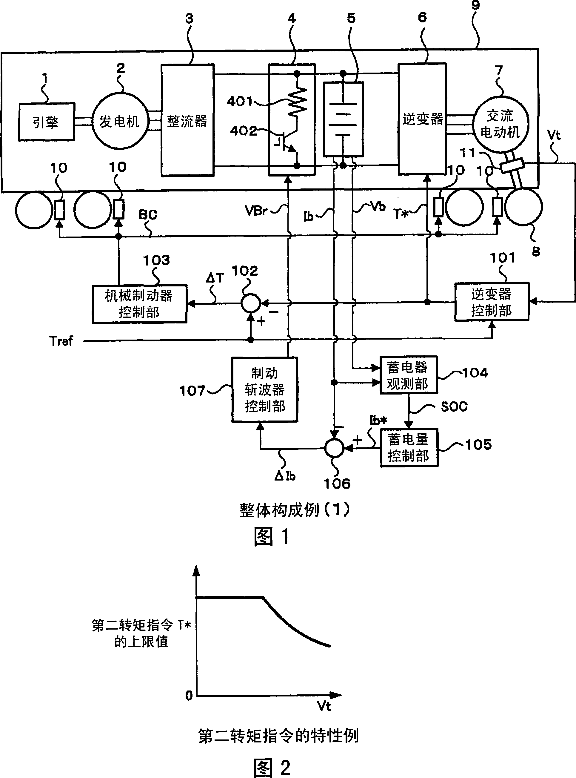
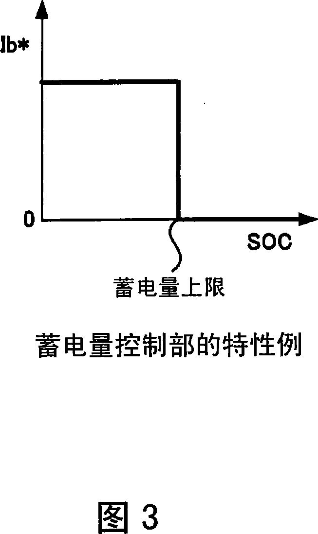
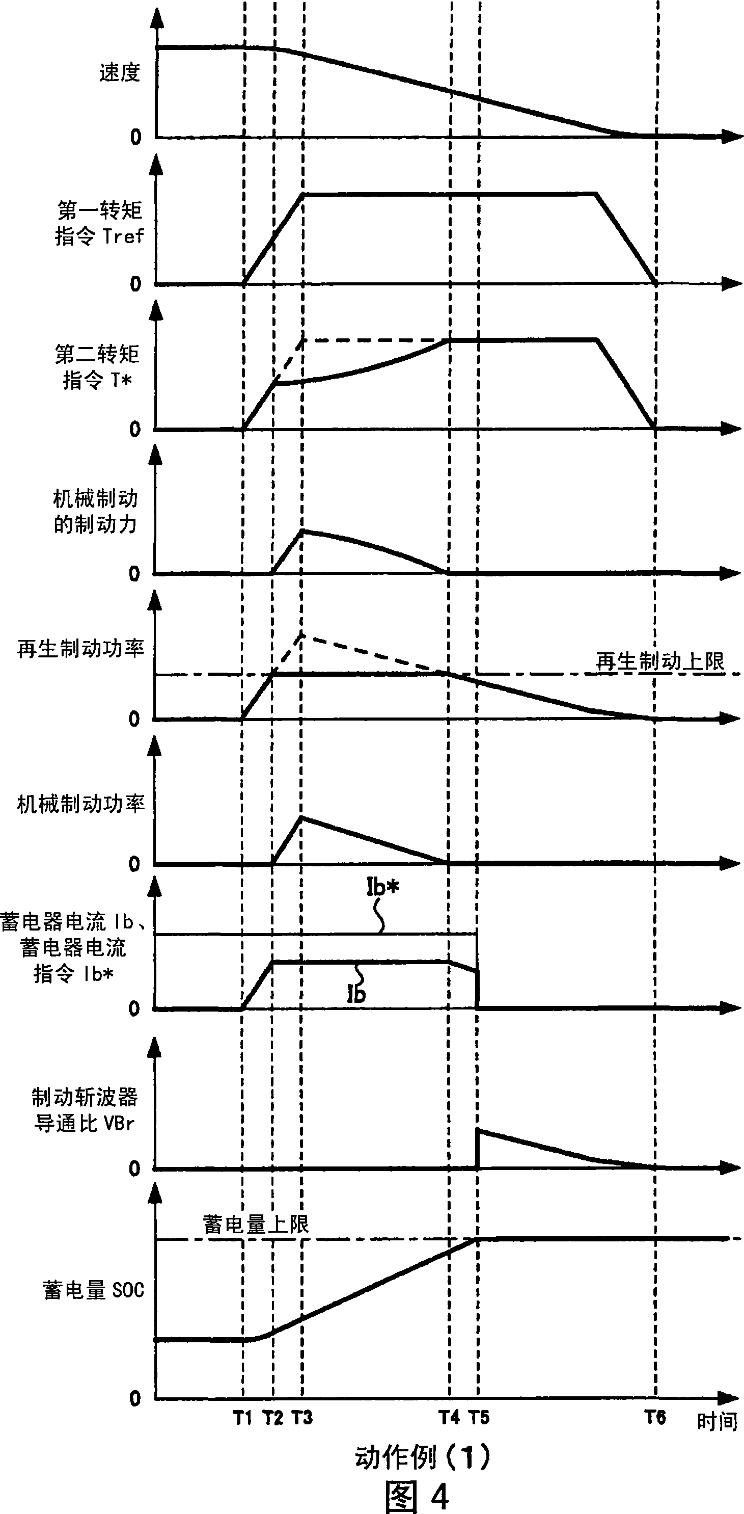
[0026] First, a first embodiment of the present invention will be described with reference to FIGS. 1 to 6 . FIG. 1 is an example of the overall configuration of the first embodiment of the present invention. This example is composed of an engine 1, a generator 2 connected to the engine 1, and a rectifier 3 that converts the generated electric power into direct current, and a brake chopper 4, an accumulator 5, and an inverter are connected in parallel to the direct current side of the rectifier 3. Device 6. The brake chopper 4 is constituted by a series circuit of a resistor 401 and a switching element 402 . In addition, as the accumulator 5, a chargeable and dischargeable battery such as a lithium ion battery is used. An AC motor 7 is connected to the inverter 6 , and the wheels 8 are driven by driving the AC motor 7 to drive the vehicle 9 . Mechanical brakes 10 are provided on the wheels 8 , and a speed detector 11 is provided on the AC motor 7 . In addition, an inverter...
Embodiment 2
[0045] Next, a second embodiment of the present invention will be described with reference to FIGS. 7 and 8 . An overall configuration example of the second embodiment is shown in FIG. 7 . In addition, the same code|symbol is attached|subjected to the same structure as FIG. 1 demonstrated in 1st Embodiment, and detailed description is abbreviate|omitted. In FIG. 7, the converter 3a is connected to the generator 2, and the converter control part 201 which controls the converter 3a is provided. On the DC side of the converter 3a, the brake chopper 4, the battery 5, and the inverter 6 are connected in parallel.
[0046] In the braking state, if the storage amount SOC exceeds the upper limit of the storage amount, the converter control unit 201 operates the converter output command P so that electric power flows from the DC side to the AC side. * , to control the converter 3a. The converter 3a is based on the output of the converter control unit 201, that is, the converter outp...
Embodiment 3
[0051] Next, a third embodiment of the present invention will be described with reference to FIG. 9 , FIG. 10 , and FIG. 11 . An overall configuration example of the third embodiment is shown in FIG. 9 . In addition, the same code|symbol is attached|subjected to the same structure as FIG. 1 demonstrated in 1st Embodiment, and detailed description is abbreviate|omitted. In this example, a current detector 301 for detecting an inverter DC current, which is a DC side current of the inverter 6, and an inverter power calculation unit 302 are provided. The inverter power calculation unit 302 calculates the inverter power Pi based on the product of the inverter DC current detected by the current detector 301 and the battery voltage Vb. Wherein, when the power is converted from the AC side to the DC side, the sign of the inverter power Pi is positive.
[0052] The stored power control unit 105a outputs the chargeable power Pb based on the stored power SOC output from the storage dev...
PUM
 Abstract
Description
Claims
Application Information
 - R&D
- Intellectual Property
- Life Sciences
- Materials
- Tech Scout
- Unparalleled Data Quality
- Higher Quality Content
- 60% Fewer Hallucinations
Browse by: Latest US Patents, China's latest patents, Technical Efficacy Thesaurus, Application Domain, Technology Topic, Popular Technical Reports.
© 2025 PatSnap. All rights reserved.Legal|Privacy policy|Modern Slavery Act Transparency Statement|Sitemap|About US| Contact US: help@patsnap.com


