Supercharge Your Innovation With Domain-Expert AI Agents!

Imaging device

A technology of an imaging device and a driving device, which is applied in the fields of imaging sensors and portable devices, and can solve the problems of increased thickness of portable devices and the inability of imaging devices to become thinner, etc.

Active Publication Date: 2008-01-09
PANASONIC CORP
View PDF2 Cites 6 Cited by
  • Summary
  • Abstract
  • Description
  • Claims
  • Application Information

AI Technical Summary

Problems solved by technology

[0007] However, the above-mentioned conventional imaging device cannot be made thinner because of the use of a compound lens, disadvantageously resulting in an increase in the thickness of a portable device having a camera.

Method used


Image

  • Imaging device
  • Imaging device
  • Imaging device

Examples


Embodiment 1

[0107] An image forming apparatus according to Embodiment 1 of the present invention will be described.

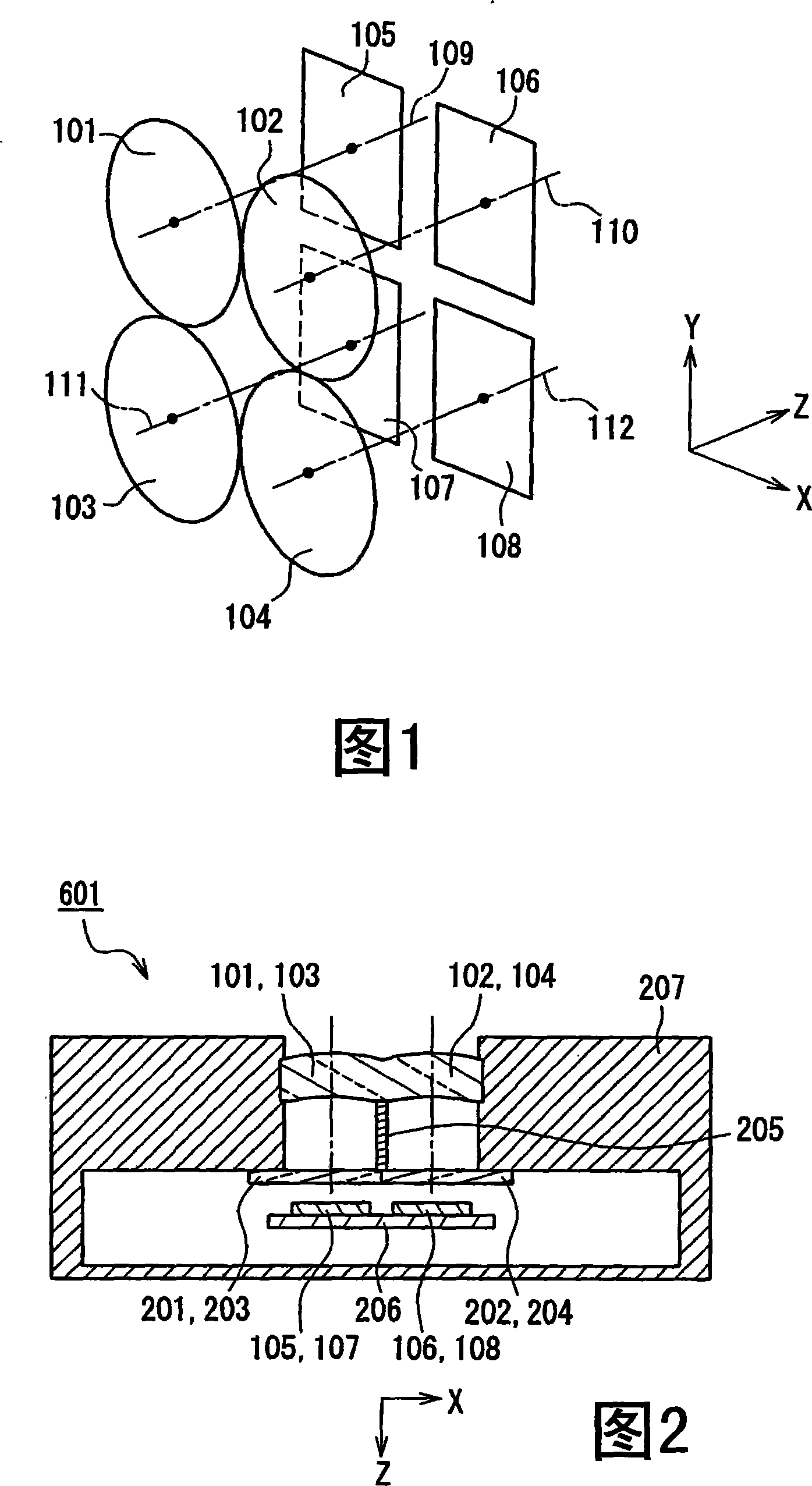
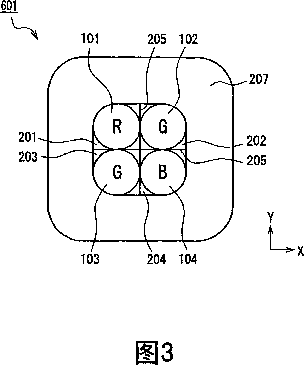
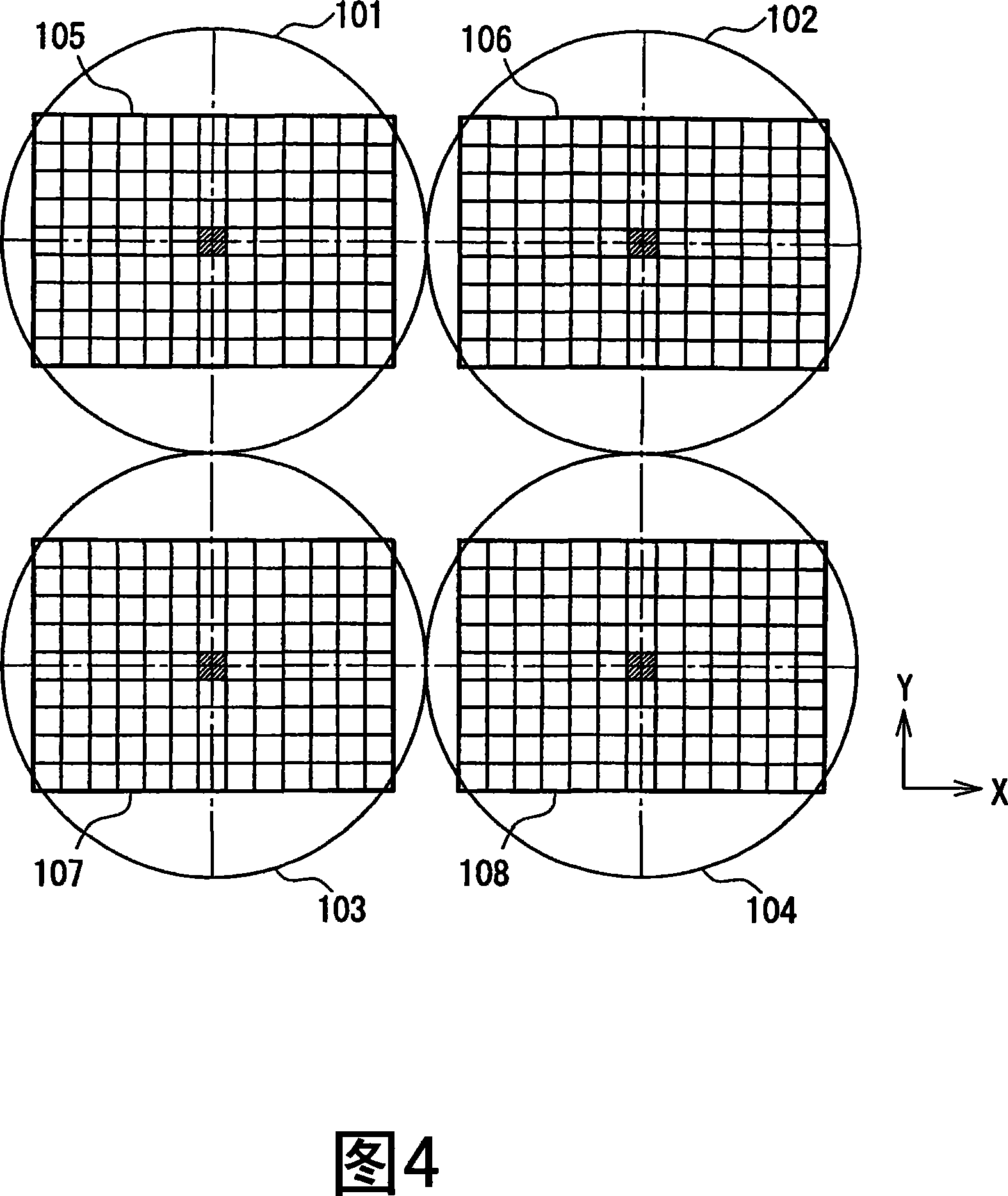
[0108] FIG. 1 is a schematic diagram of an imaging device according to Embodiment 1 of the present invention. Fig. 2 is a cross-sectional view of an image forming apparatus according to Embodiment 1 of the present invention. 3 is a plan view of the imaging device of Embodiment 1 of the present invention viewed from the lens side.

[0109] In FIG. 1 , the imaging device of Embodiment 1 has four single lenses 101 , 102 , 103 , and 104 , and four imaging sensors 105 , 106 , 107 , and 108 corresponding thereto. As shown in Figure 1, the direction of the optical axes 109, 110, 111 and 112 of the single lenses 101, 102, 103, and 104 is represented as the Z axis, the direction perpendicular to the Z axis is represented as the X axis, and the direction perpendicular to the X axis and The direction of the Z axis is represented as a Y axis. The positive directions of the X-axis, ...

Embodiment 2

[0206] A diffraction grating lens in which a diffraction grating is formed on a lens surface will be described. Blazed diffraction gratings are preferred for improved efficiency. However, a blazed grating optimized for a certain wavelength band (for example, green) has high diffraction efficiency for that wavelength band, but poor efficiency for other wavelength bands (for example, red or blue), causing unnecessary light. Imaging systems need to be highly efficient in the green, red and blue bands. Therefore, the use of diffraction gratings in imaging systems has limitations.

[0207] However, in the imaging device of Embodiment 2, a plurality of lens systems and the same number of imaging sensors are arranged in such a manner that the imaging sensors are arranged on the optical axis of each lens system in the same manner as in Embodiment 1. Each lens system corresponds to only one red, green or blue band. Therefore, a blazed diffraction grating optimized for each wavelengt...

Embodiment 3

[0212] Although four imaging sensors are used in Embodiment 1, a single imaging sensor divided into four imaging regions may be used.

[0213] The structure of an image forming apparatus according to Embodiment 3 of the present invention will be described below.

[0214] Fig. 25 is a schematic diagram of an image forming apparatus according to Embodiment 3 of the present invention. Fig. 26 is a top view showing a lens system and an imaging sensor in the imaging device of Embodiment 3 of the present invention. Fig. 27 is a sectional view of an image forming apparatus according to Embodiment 3 of the present invention. In FIGS. 25 to 27, the same components as those in FIGS. 1 to 24 are denoted by the same reference numerals and will not be described again.

[0215] In FIG. 25 , the imaging device has four single lenses 101 , 102 , 103 , and 104 , and a single imaging sensor 900 . Similar to Fig. 1, the direction of the optical axes 109, 110, 111 and 112 of the single lenses ...


PUM


Abstract

A plurality of imaging regions (105-108) are provided in one-to-one correspondence with a plurality of optical systems (101-104) and are disposed on optical axes of the respective optical systems. Each imaging region (105-108) has a plurality of pixels. The imaging apparatus further comprises an origin detecting means for detecting an origin of each imaging region (105-108), a pixel position specifying means for specifying positions of a plurality of pixels included in each imaging region (105-108) using the origin as a reference, and a combination means for combining a plurality of images captured by the respective imaging regions (105-108). Thereby, it is possible to make a thin imaging apparatus capable of being easily assembled.

Description

[0001] This application is a divisional case of an invention patent application with an application date of September 30, 2004, an application number of 200480002447.7, and an invention title of "imaging device and its production method, portable equipment, and imaging sensor and its production method". field of invention [0002] The present invention relates to a compact image forming device capable of obtaining clear color images and a production method thereof. The invention also relates to a portable device comprising the imaging device. The invention also relates to an imaging sensor used in the imaging device and a production method thereof. technical background [0003] Portable devices, such as mobile phones with cameras, have become very popular. As portable devices become smaller, thinner and more functional, smaller, thinner and more functional imaging devices are required. [0004] Conventionally, a known imaging device uses a compound lens and an imaging sens...

Claims


Application Information

Patent Timeline
Patent Type & Authority Applications(China)
IPC IPC(8): H04N5/225H04N5/232G02B13/00H04N23/12H04N25/00
Inventor 永岛道芳今田胜巳西胁青儿
Owner PANASONIC CORP
Features
  • R&D
  • Intellectual Property
  • Life Sciences
  • Materials
  • Tech Scout
  • Unparalleled Data Quality
  • Higher Quality Content
  • 60% Fewer Hallucinations
Learn More