Check patentability & draft patents in minutes with Patsnap Eureka AI!

An indoor distributed system for supporting real time network optimization and its implementation method

A distributed system and network technology, which is applied to the indoor distributed system and its implementation field that supports real-time network optimization, can solve the problems of community load fluctuations, large space attenuation loss, indoor coverage system cost pressure, etc., to increase system capacity , the effect of saving network resources

Active Publication Date: 2008-01-09
ZTE CORP
View PDF0 Cites 40 Cited by
  • Summary
  • Abstract
  • Description
  • Claims
  • Application Information

AI Technical Summary

Problems solved by technology

The frequency of 3G wireless network is concentrated at 2.1GHz, and high frequency brings excessive space attenuation loss
[0006] However, in actual 3G indoor applications, due to the existence of many high-speed application types, the load of the cell changes greatly at different times, the functions of different areas in the building change, and the different functional areas in the building at different times Changes in the density of people will cause fluctuations in the load of the community
If the network planning is planned according to the peak application, the cost of the indoor coverage system will be under great pressure

Method used


Image

  • An indoor distributed system for supporting real time network optimization and its implementation method
  • An indoor distributed system for supporting real time network optimization and its implementation method
  • An indoor distributed system for supporting real time network optimization and its implementation method

Examples


Embodiment 1

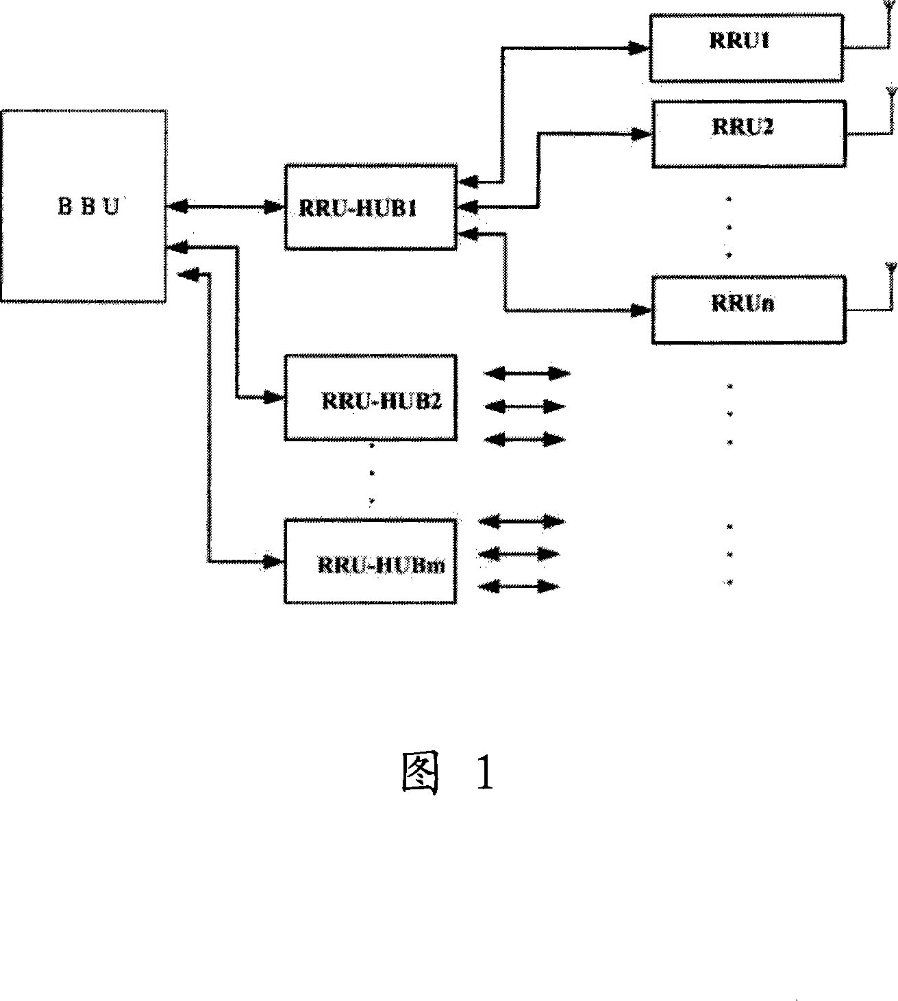
[0030] Embodiment 1 provides an indoor distributed system that supports real-time network optimization. As shown in Figure 1, the system includes a BBU, multiple RRU-HUBs, and multiple Pico-RRUs, where the BBU is connected to multiple HUB, each RRU-HUB is connected to multiple Pico-RRUs. The downlink direction of the system is that the RRU-HUB receives the downlink data of the BBU and distributes it to each Pico-RRU at the same time; the uplink direction is that after the RRU-HUB receives the data of all Pico-RRUs, it sends the data to the BBU after data combining.

[0031] Among them, the BBU mainly completes functions such as uplink and downlink baseband processing, clock processing, and interface with the base station controller.

[0032] RRU-HUB is mainly used to realize the collection and exchange of baseband data.

[0033] The Pico-RRU mainly completes the conversion of downlink baseband signals to RF signals and the transmission of RF signals, the reception of uplink R...

Embodiment 2

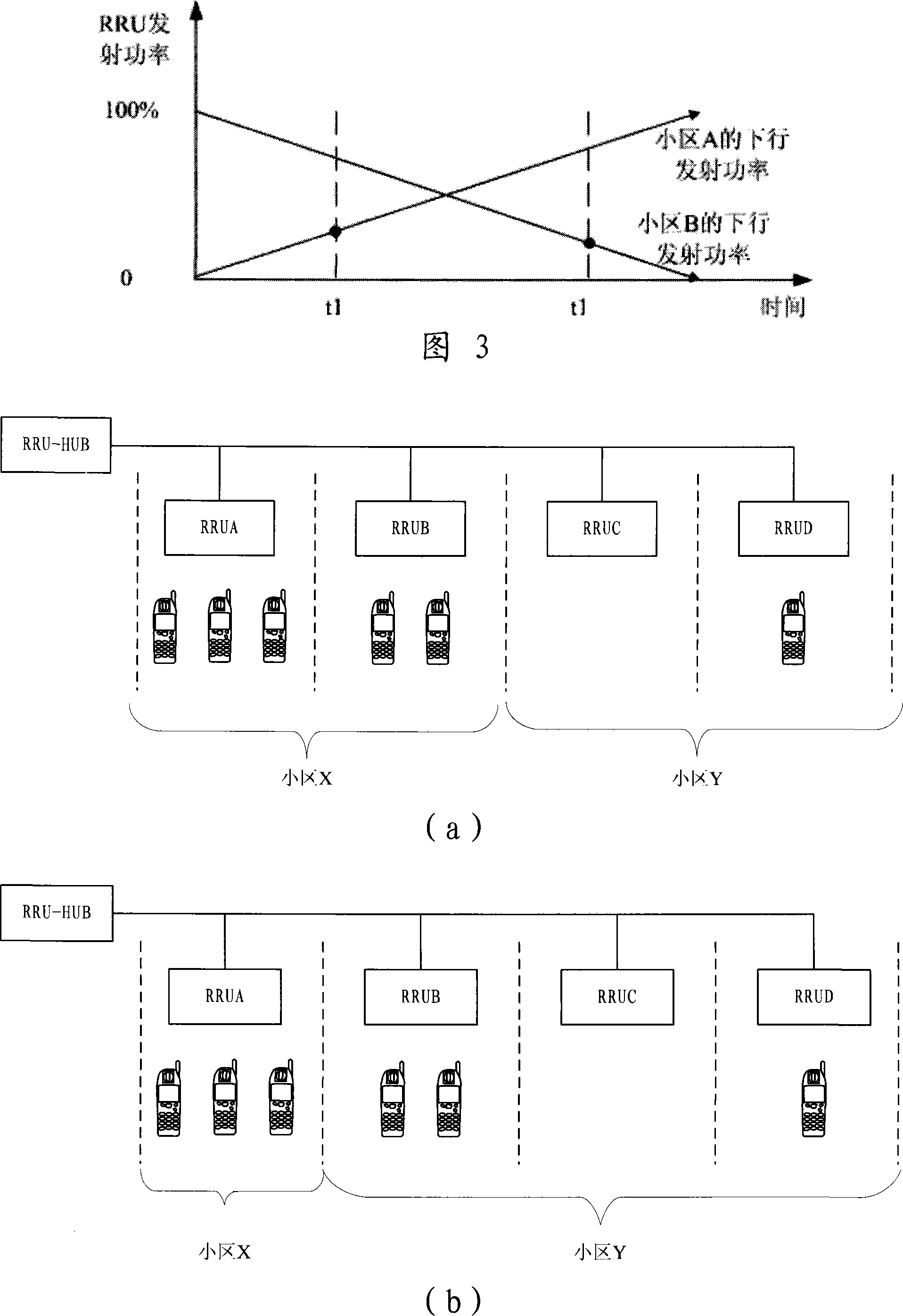
[0057] Embodiment 2 provides an indoor distributed system that realizes real-time network optimization through cell splitting and merging. Figure 4(a) is a schematic diagram of the structure of the cell coverage system without optimization in Embodiment 2. In this system, four Pico-RRUs are connected behind the RRU-HUB, which are RRUA, RRUB, RRUC, and RRUD, and RRUA and RRUB support both Cell X, RRUC and RRUD support cell Y. At this time, the number of users accessed in cell X is relatively large, while the number of users accessed in cell Y is small.

[0058] In the system shown in Figure 4(a), the RRUB downlink transmission content is switched from the downlink signal of cell X to the downlink signal of cell Y, so that the mobile station in the coverage area of ​​RRUB is brought to cell Y, and the figure 4 ( b) shows a schematic diagram of the optimized system structure, where RRUA alone supports a cell X, and RRUB, RRUC, and RRUD together support a cell Y, and the user vol...


PUM


Abstract

The method comprises: in the first, the system uses the baseband unit (BBU) to control Pico-remote radio unit (Pico-RRU) to transmit signals in order to make two neighboring co-frequency cells simultaneously cover one fixed area; then system controls the transmission power ratio of two cells to make the soft-switch for the mobile station in said fixed area. The invention also provides an indoor distribution system supporting the network real-time optimization.

Description

technical field [0001] The invention relates to the field of communication technology, in particular to an indoor distributed system and an implementation method supporting real-time network optimization. Background technique [0002] With the gradual development of 3G wireless network applications worldwide, 3G indoor coverage is on the agenda, and major operators have begun to pay attention to 3G indoor coverage. According to the analysis of NTT DoCoMo Company in Japan, it is found that the usage of 3G indoor services is as high as 69.7% of the total business volume, so good indoor coverage is the key factor for whether 3G services can capture users. [0003] 3G networks must achieve high enough coverage to be attractive to users. 3G services will first be applied in places with market potential, such as central areas of big cities, business districts, or densely populated areas such as airports, hotels, and subways. The frequency point of 3G wireless network is concentr...

Claims


Application Information

Patent Timeline
Patent Type & Authority Applications(China)
IPC IPC(8): H04Q7/38H04B7/26H04W16/20
Inventor 高嵩张文国由武军
Owner ZTE CORP
Features
  • R&D
  • Intellectual Property
  • Life Sciences
  • Materials
  • Tech Scout
  • Unparalleled Data Quality
  • Higher Quality Content
  • 60% Fewer Hallucinations
Learn More