Controllable silicon trigger circuit of continuous mouse trapping boxes

A trigger circuit and mouse trap technology, applied in electronic switches, electrical components, animal traps, etc., can solve problems such as the inability to freely switch the working voltage, the inability to stop the alarm sound, and the error of the delay circuit of the mouse trap. Ease of implementation, low power consumption, and low component count

Inactive Publication Date: 2008-01-16
EAST CHINA NORMAL UNIV
View PDF0 Cites 8 Cited by
  • Summary
  • Abstract
  • Description
  • Claims
  • Application Information

AI Technical Summary

Problems solved by technology

[0002] At present, the mousetrap control circuit on the market generally has various deficiencies: it cannot automatically recover after being triggered by mistake; the alarm sound cannot stop by itself; the sensitivity is not high; the delay circuit of the mousetrap has a large error; Poor safety performance; large current during standby; working voltage cannot be freely switched to AC or DC, etc.

Method used


Image

  • Controllable silicon trigger circuit of continuous mouse trapping boxes
  • Controllable silicon trigger circuit of continuous mouse trapping boxes
  • Controllable silicon trigger circuit of continuous mouse trapping boxes

Examples


Embodiment 1

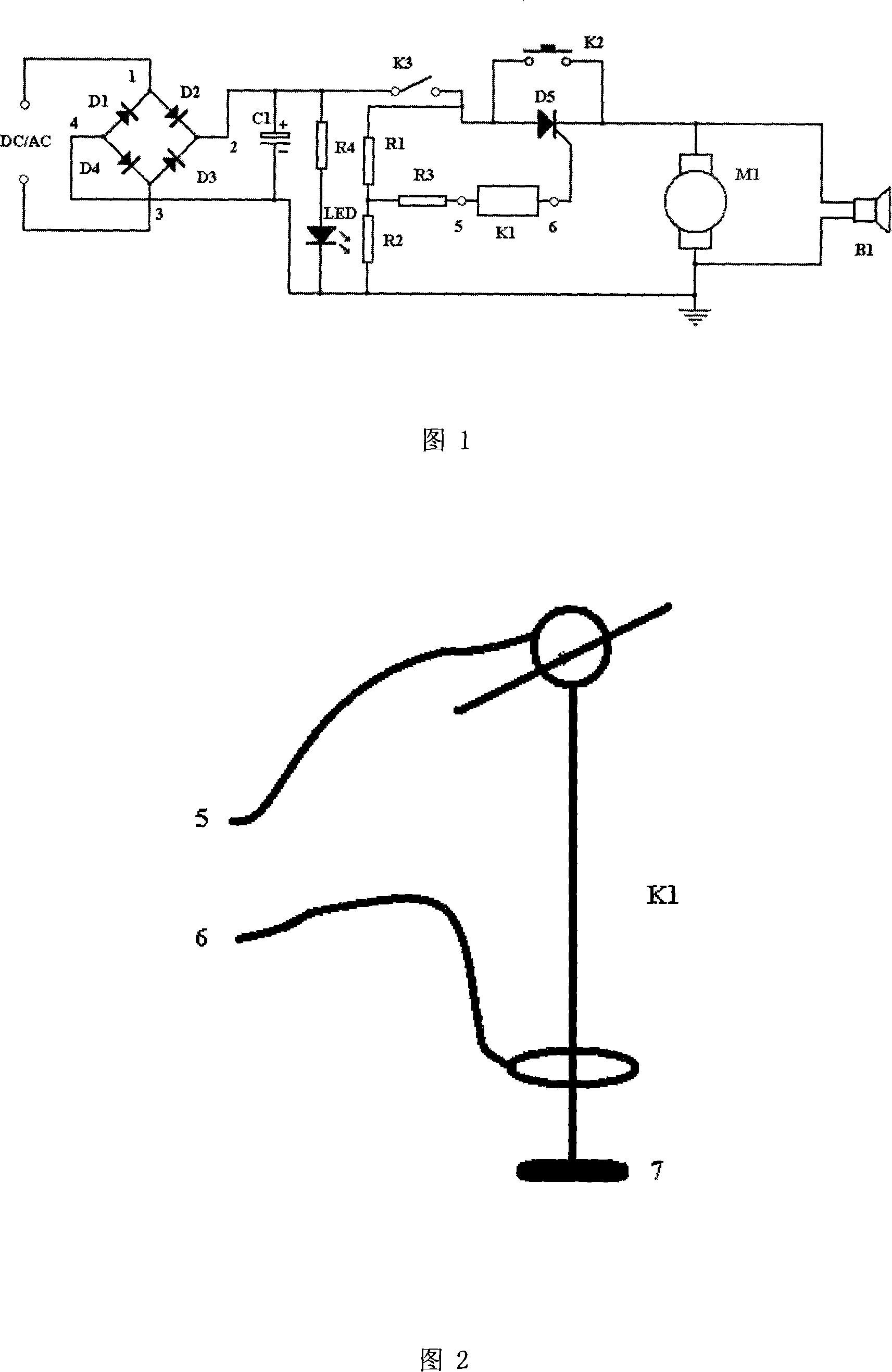
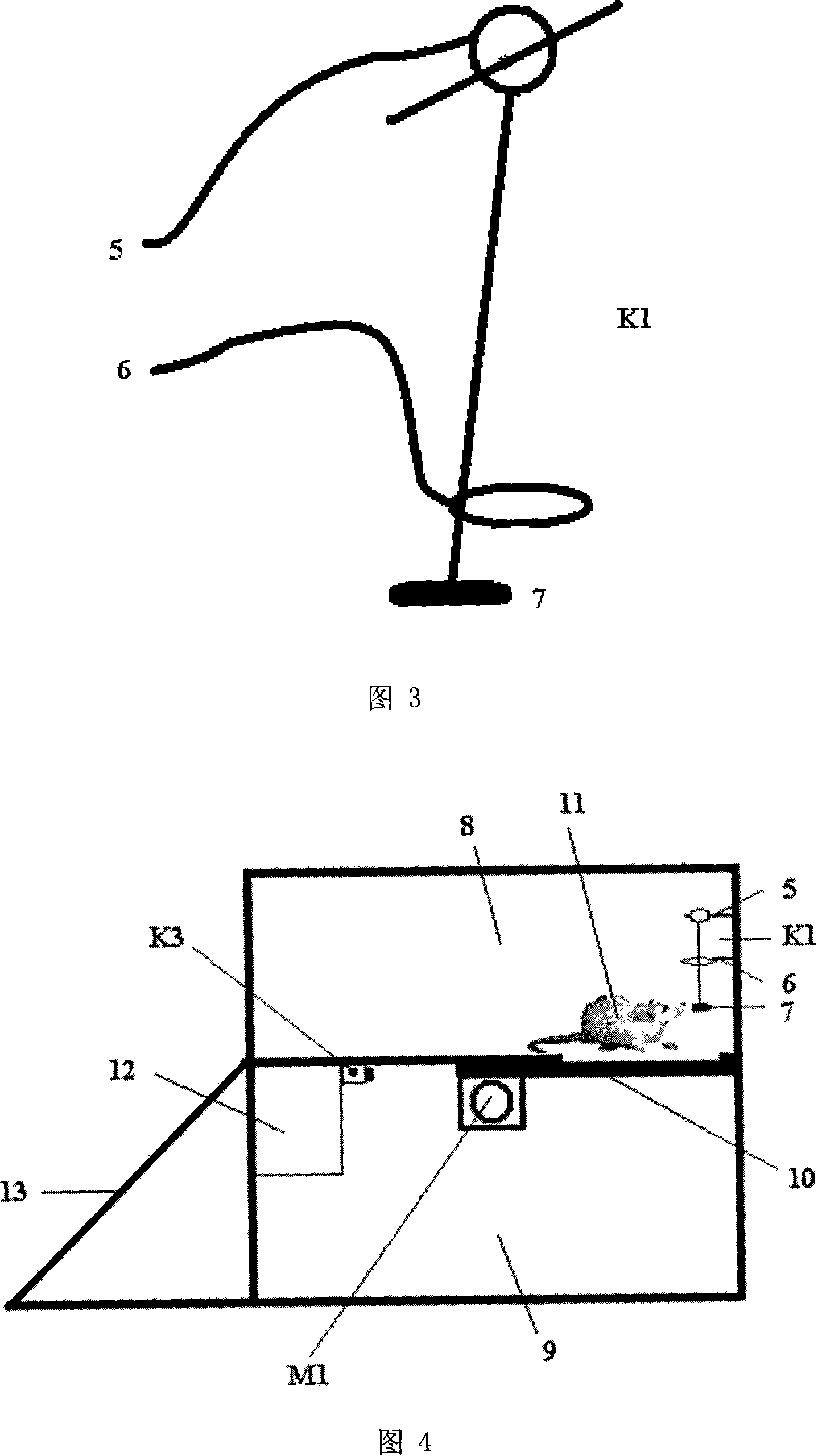
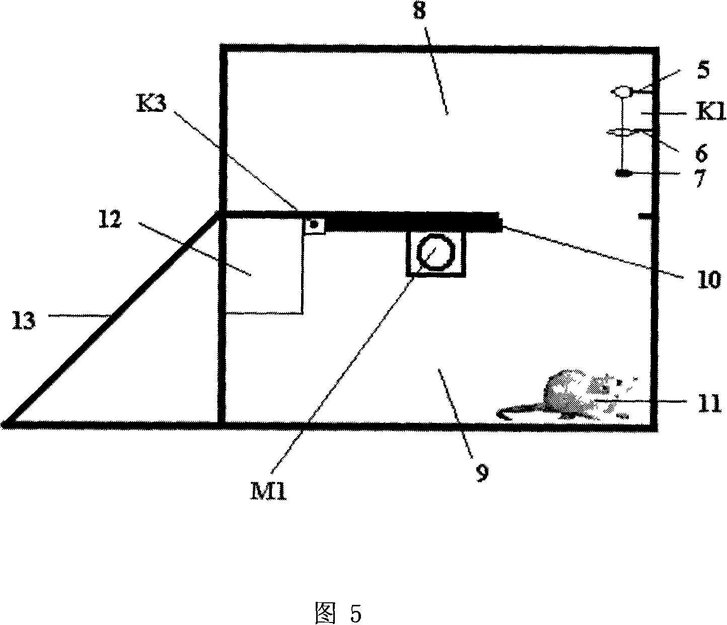
[0020] A thyristor trigger circuit 12 of a continuous mouse trap needs to be used in combination with a motor-driven continuous mouse trap. The cage 9 is closed, the upper floor mouse cage 8 is open, and there is a pumping plate 10 between the two layers. The step 13 is a closed surface of the lower floor mouse cage 9, which is obliquely connected to the front bottom edge of the upper floor mouse cage 8 and the lower floor mouse cage. Between the front bottom of the cage 9, the thyristor trigger circuit 12 contains the motor M1 and the working power supply. The thyristor trigger circuit 12 is installed in the lower squirrel cage 9, and the motor M1 draws the drawer by winding a steel wire around its rotating shaft when it is working. 10 is installed in the lower squirrel cage 9 in a manner of translation along the horizontal direction, and the negative output end of the working power supply is grounded. It is connected with the first power input terminal 1 and the second power...

Embodiment 2

[0022] Except for the following differences, this embodiment has exactly the same structure as Embodiment 1. It is characterized in that the thyristor trigger circuit 12 also includes a buzzer B1, and the positive pole and negative pole of the buzzer B1 are respectively connected to the positive terminal of the motor M1. Connect to the negative terminal.

Embodiment 3

[0024] Except for the following differences, this embodiment has the same structure as Embodiment 1. It is characterized in that the thyristor trigger circuit 12 also includes a normally open switch K2, which is a push button switch and is connected across the thyristor D5 between the anode and cathode.


PUM


Abstract

A SCR trigger circuit of continuous mousetrap belongs to the electric control technology field. At present, the deficiencies are widely existed in the mousetrap control circuits of the market, such as the lack of self recovery after the false triggering, the lack of self-stopping of the alarm sound, the low sensitivity, the large standby power and so on. The SCR trigger circuit is in the utilization of a SCR control motor to work. When a mouse touches the mechanical sensor, the triggering voltage is in conduction through the triggering of the occlusive mechanical sensor to the SCR, and the pulling tray is driven through the rotation of the motor to open. When the pulling tray is completely open, the closing contact of the normally closed switch in series connection in the power supply circuit is daffed, so that the SCR can be in cut-off due to the loss of power. The pulling tray is driven through a compression spring to be in self-closing, thus the SCR trigger circuit gets back to the standby status for the next mouse capture. The utility model has the advantages of self recovery after the false triggering, alarm sound self-stopping, high sensitivity, very low standby power, which can work with AC or DC power supply.

Description

technical field [0001] The invention relates to a thyristor trigger circuit of a continuous mouse trap, which belongs to the technical field of electronic automatic control. Background technique [0002] At present, the mousetrap control circuit on the market generally has various deficiencies: it cannot automatically recover after being triggered by mistake; the alarm sound cannot stop by itself; the sensitivity is not high; the delay circuit of the mousetrap has a large error; Poor safety performance; large current during standby; working voltage cannot be freely switched to AC or DC. Contents of the invention [0003] The technical problem to be solved by the invention is to introduce a thyristor trigger circuit for a continuous mouse trap. This circuit does not have the common shortcomings of the current mousetrap control circuit. It will automatically resume the standby state after being triggered by mistake. The trigger sensitivity is high, and the standby power con...

Claims


Application Information

Patent Timeline
Patent Type & Authority Applications(China)
IPC IPC(8): A01M23/14G05B11/01H03K17/72G08B21/18
Inventor 张健李俊君
Owner EAST CHINA NORMAL UNIV
Why Eureka
Try Eureka