High-frequency heater

A high-frequency heating and equipment technology, applied in microwave heating, electric/magnetic/electromagnetic heating, electric heating devices, etc., can solve problems such as unstable operation, and achieve the effect of reducing high-order harmonic distortion

Active Publication Date: 2008-01-16
PANASONIC CORP
View PDF3 Cites 0 Cited by
  • Summary
  • Abstract
  • Description
  • Claims
  • Application Information

AI Technical Summary

Problems solved by technology

[0023] It should be noted that when the switching frequency is very close to the resonance frequency "f0", causing unstable operation such as abnormal resonance

Method used


Image

  • High-frequency heater
  • High-frequency heater
  • High-frequency heater

Examples


Embodiment 1

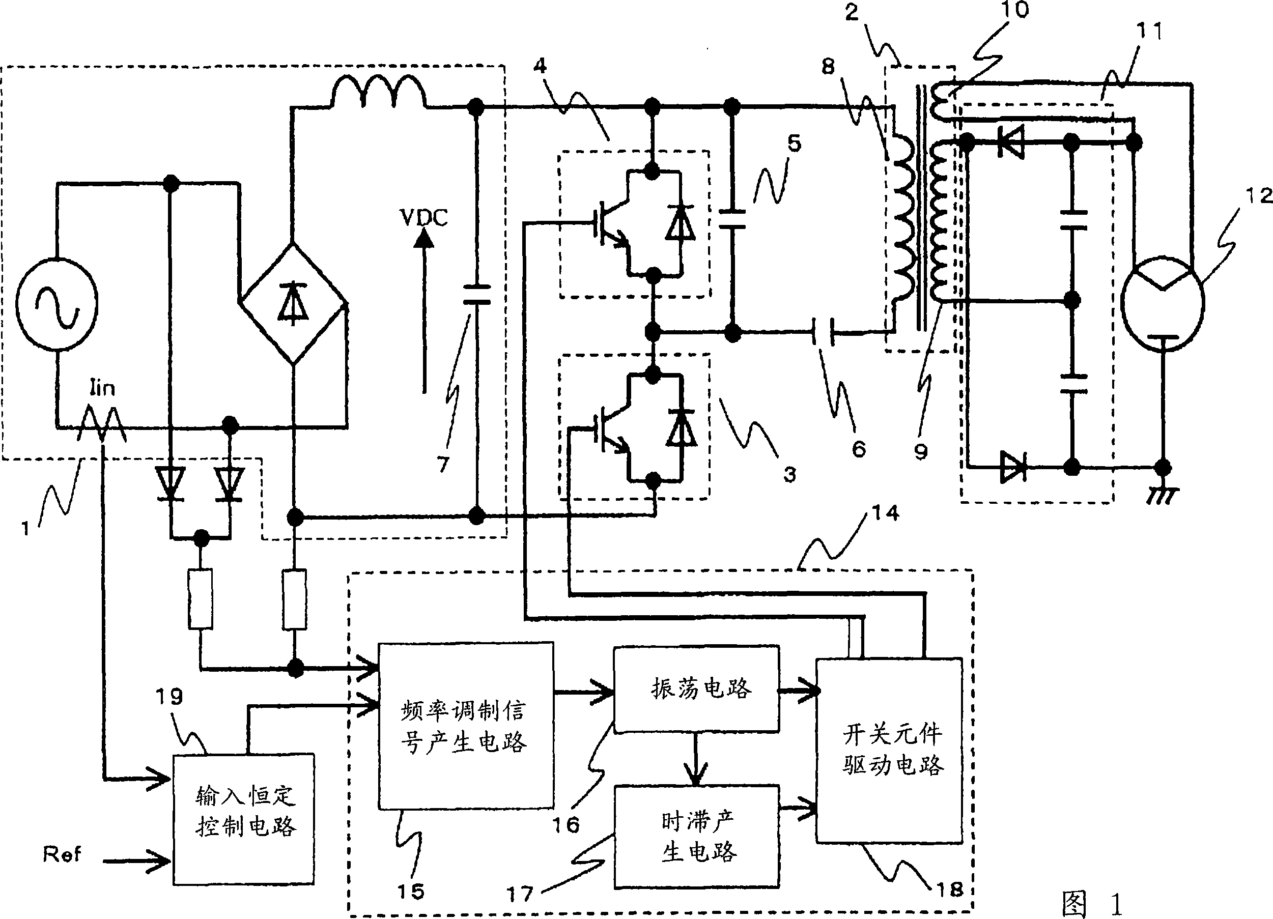
[0077] FIG. 1 shows a circuit diagram of a magnetron drive power supply circuit of a high frequency heating device according to a first embodiment of the present invention. In the inverter circuit, by using the DC power supply 1, the leakage transformer 2, the first semiconductor switching element 3, the first capacitor (snubber capacitor) 5, the second capacitor (resonance capacitor) 6, the third capacitor (smoothing capacitor) 7. The second semiconductor switching element 4, the driving circuit 14, the full-wave power supply double rectification circuit 11 and the magnetron 12 constitute the main circuit. Since the arrangements of the above-described main circuits other than the drive circuit 14 are the same as those of FIG. 11 , explanations thereof are omitted.

[0078] In the drive circuit 14 for driving the first and second semiconductor switching elements 3 and 4, first, a frequency modulation waveform is formed by the frequency modulation signal generation circuit 15 b...

Embodiment 2

[0088] FIG. 5 indicates a frequency modulation signal generating circuit employed in a magnetron-driven inverter circuit of a second embodiment of the present invention, which is different from the first embodiment described above in that a resistor 155 is newly provided. According to this embodiment, the second limiting function can be realized by limiting the variation of the frequency modulation waveform by gradually increasing the sensitivity due to the separation of the frequency from V2 in lower than or equal to the fixed voltage V2 (claim 5).

[0089] Fig. 6 shows frequency modulation waveforms of the second embodiment. Similar to the first embodiment, the waveform change around the lowest frequency becomes smooth, so that sudden changes in frequency can be suppressed.

Embodiment 3

[0091] FIG. 7 indicates a frequency modulation signal generating circuit employed in a third embodiment of the present invention, which is different from the first embodiment described above in that a transistor 159 is provided in the first limiting circuit.

[0092] According to this third embodiment, the change in the resistance value of the PN junction indicated by the voltage versus current characteristic is adopted by the resistor 159 as a first limiting function (claim 6).

[0093] When the potential difference of the PN junction increases, the resistance value of the PN junction decreases. As a result, since the potential of the divided waveform obtained by rectifying the commercial power supply voltage becomes lower than the voltage V1 and separated from this voltage B1, the sensitivity of the first limiting function rises so that the waveform lower than or equal to V1 is smoothly changed .

[0094] In addition, although a plurality of sets of first restriction functi...


PUM


Abstract

A high-frequency heating power supply for driving a magnetron such as a microwave oven and a frequency modulating method for reducing the power supply harmonic distortion of high orders caused at the phases of about 0 and 180 degrees at which the instantaneous voltage of the commercial power supply is the lowest are provided. When the high-frequency heating power supply gives a signal for driving first and second semiconductor switching elements (3, 4),the high-frequency heating power supply suppresses the power supply harmonic distortion of high order by smoothly varying the switching frequency near the boundary between the period during which the lowest switching frequency is limited to f1 at the phases of about 0 and 180 degrees at which the instantaneous voltage of the commercial power supply is the lowest and the period during which the limitation is canceled, that is, by eliminating a sharp variation of the switching frequency.

Description

technical field [0001] The present invention relates to high-frequency heating equipment using a magnetron, such as a microwave oven. More particularly, the present invention relates to a control system for suppressing harmonic distortion of a commercial power supply current supplied to a magnetron drive power supply. Background technique [0002] Since a conventional power supply mounted on a high-frequency heating device is heavy and bulky, it is required to make the power supply compact and lightweight. For this reason, various active methods capable of constructing such a low-cost, compact, and light-weight switching power supply have been proposed in various fields at present. In a high-frequency heating apparatus for cooking food by using microwaves generated from a magnetron, a compact and lightweight power supply for driving the magnetron, which can be realized by a switching inverter circuit, is required. [0003] More specifically, among these switching-type inve...

Claims


Application Information

Patent Timeline
Patent Type & Authority Applications(China)
IPC IPC(8): H05B6/68
CPCH05B6/685Y02B40/143Y02B40/00
Inventor 末永治雄守屋英明酒井伸一城川信夫木下学
Owner PANASONIC CORP
Why Eureka
Try Eureka