High-frequency heater
A high-frequency heating and equipment technology, applied in microwave heating, electric/magnetic/electromagnetic heating, electric heating devices, etc., can solve problems such as unstable operation, and achieve the effect of reducing high-order harmonic distortion
- Summary
- Abstract
- Description
- Claims
- Application Information
AI Technical Summary
Problems solved by technology
Method used
Image
Examples
Embodiment 1
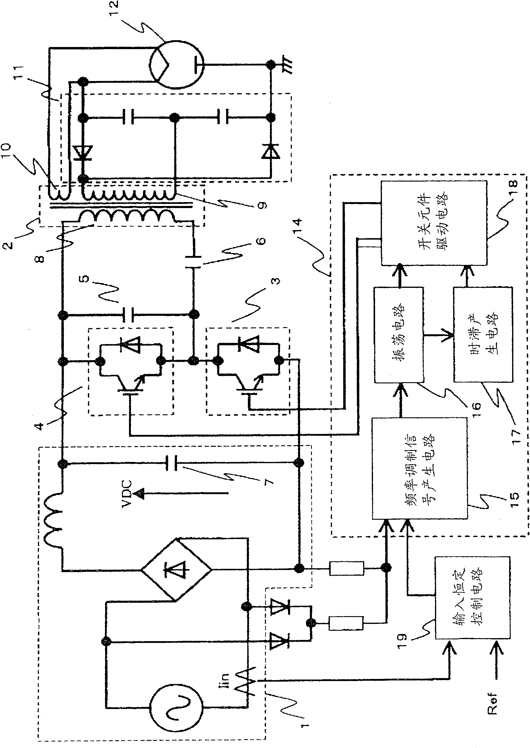
[0077] figure 1 A circuit diagram of the magnetron drive power circuit of the high-frequency heating device according to the first embodiment of the present invention is shown. In the inverter circuit, by using the DC power supply 1, the leakage transformer 2, the first semiconductor switching element 3, the first capacitor (snubber capacitor) 5, the second capacitor (resonant capacitor) 6, the third capacitor (smoothing capacitor) 7. The second semiconductor switching element 4, the driving circuit 14, the full-wave power double rectifier circuit 11 and the magnetron 12 constitute its main circuit. Due to the arrangement of the above-mentioned main circuit other than the drive circuit 14 and Picture 11 Those are the same, so its explanation is omitted.
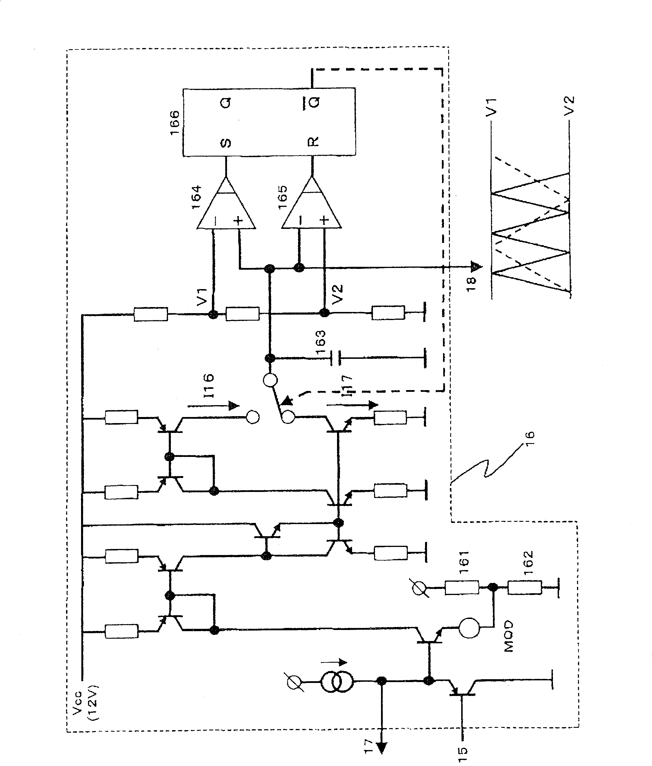
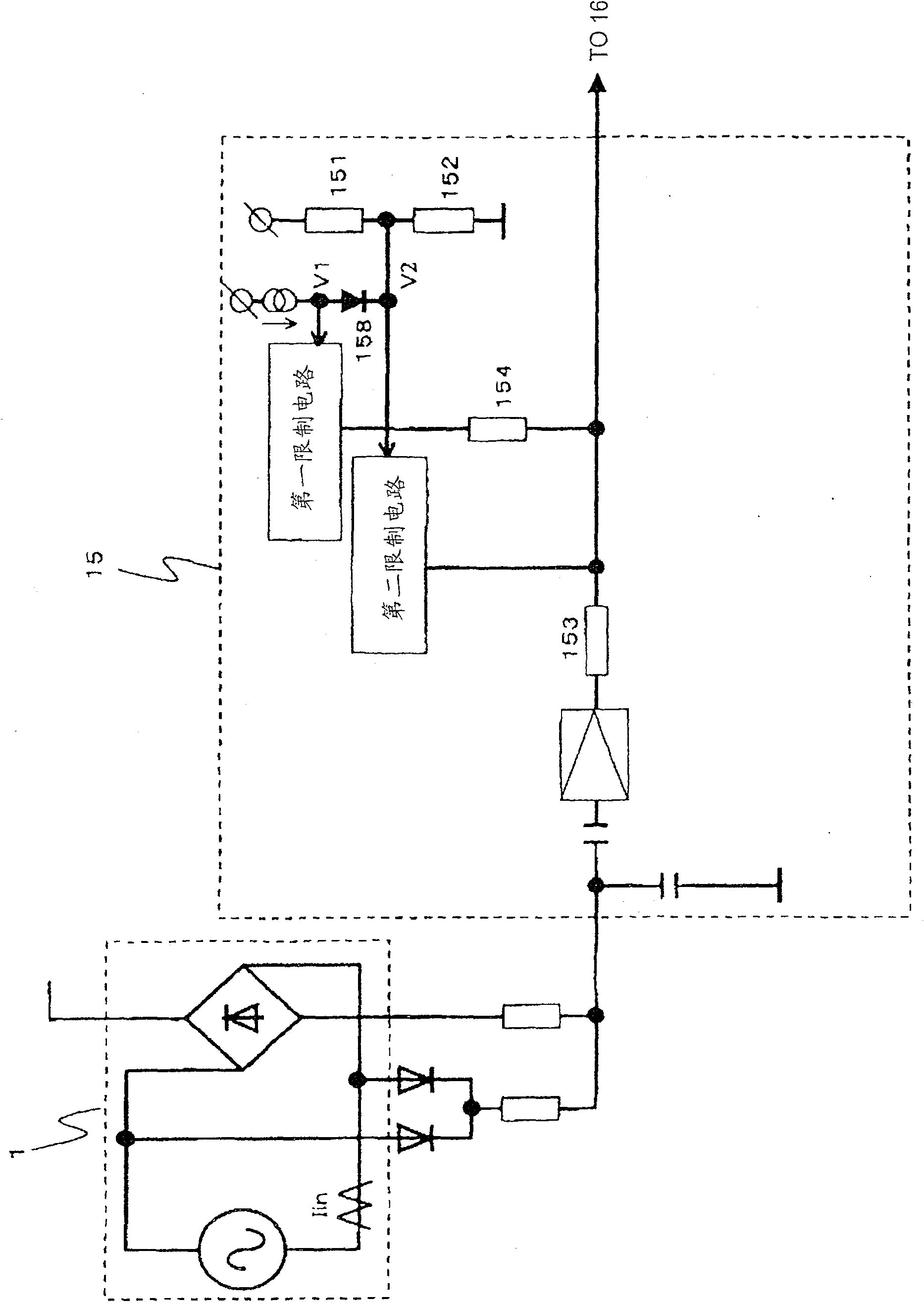
[0078] In the driving circuit 14 for driving the first and second semiconductor switching elements 3 and 4, first, the frequency modulation signal generating circuit 15 forms a frequency modulation waveform by using a waveform ...
Embodiment 2
[0088] Figure 5 It is indicated that the frequency modulation signal generating circuit adopted in the magnetron-driving inverter circuit of the second embodiment of the present invention is different from the above-mentioned first embodiment in that a resistor 155 is newly provided. According to this embodiment, by separating the frequency from V2 when the voltage is lower than or equal to the fixed voltage V2, the second limiting function can be realized by gradually increasing the sensitivity to limit the change of the frequency modulation waveform.
[0089] Image 6 The frequency modulation waveform of the second embodiment is shown. Similar to the first embodiment, the waveform change in the vicinity of the lowest frequency becomes smooth, making it possible to suppress sudden changes in frequency.
Embodiment 3
[0091] Figure 7 It is indicated that the frequency modulation signal generating circuit adopted in the third embodiment of the present invention is different from the above-mentioned first embodiment in that a transistor 159 is provided in the first limiting circuit.
[0092] According to this third embodiment, the resistance value change of the PN junction indicated by the voltage versus current characteristic is adopted by the resistor 159 as the first limiting function.
[0093] When the potential difference of the PN junction increases, the resistance value of the PN junction decreases. As a result, since the potential of the divided voltage waveform obtained by rectifying the commercial power supply voltage becomes lower than the voltage V1 and separated from the voltage B1, the sensitivity of the first limiting function increases, so that the voltage lower than or equal to V1 is smoothly changed Waveform.
[0094] In addition, although multiple sets of first restriction funct...
PUM
 Abstract
Description
Claims
Application Information
 - R&D
- Intellectual Property
- Life Sciences
- Materials
- Tech Scout
- Unparalleled Data Quality
- Higher Quality Content
- 60% Fewer Hallucinations
Browse by: Latest US Patents, China's latest patents, Technical Efficacy Thesaurus, Application Domain, Technology Topic, Popular Technical Reports.
© 2025 PatSnap. All rights reserved.Legal|Privacy policy|Modern Slavery Act Transparency Statement|Sitemap|About US| Contact US: help@patsnap.com


