Acoustic device and electronic apparatus

A technology for acoustic devices and electronic equipment, applied in the field of acoustic devices and electronic equipment, can solve the problems of negative effect on the sensitivity of the acoustic system, affect the service life of the speaker unit, and damage the acoustic performance of the speaker unit, so as to improve the sensitivity of the low frequency band and the sensitivity of the low frequency , the effect of reducing the resonance frequency

Active Publication Date: 2020-02-25
GOERTEK INC
View PDF10 Cites 1 Cited by
  • Summary
  • Abstract
  • Description
  • Claims
  • Application Information

AI Technical Summary

Problems solved by technology

However, there are problems in the above two methods. The first method of adding sound-absorbing materials to the cabinet needs to achieve good sealing and packaging of the sound-absorbing materials. Otherwise, if the sound-absorbing materials enter the speaker unit, it will damage the acoustic performance of the speaker unit and affect the speaker unit. The service life of the second type of passive radiator is adopted. Near the resonant frequency point fp, the passive radiator radiates strongly, and the sound unit almost stops. Therefore, the high-sensitivity

Method used


Image

  • Acoustic device and electronic apparatus
  • Acoustic device and electronic apparatus
  • Acoustic device and electronic apparatus

Examples


Embodiment 1

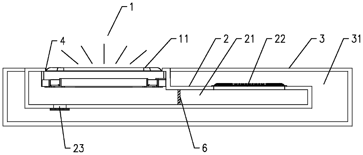
[0045] Such as Figure 3A As shown, an acoustic device includes a sounding unit 1, wherein, in this embodiment, the sounding unit 1 is a miniature sounding unit, more specifically, the sounding unit 1 is a miniature moving coil speaker. The sound unit 1 generally includes a housing and a vibration system and a magnetic circuit system fixed in the housing. The vibration system includes a vibrating diaphragm 11 fixed on the housing and a voice coil combined with the vibrating diaphragm 11. The magnetic circuit system is formed with The magnetic gap, the voice coil is set in the magnetic gap, and the voice coil reciprocates up and down in the magnetic field after being fed with alternating current, thereby driving the vibrating diaphragm 11 to vibrate and produce sound.

[0046] The acoustic device is provided with a sound outlet 4, and the sound waves on the front side of the vibrating membrane 11 are radiated to the outside through the sound outlet 4, and the sound waves on the...

Embodiment 2

[0077] The main difference between this embodiment and the above-mentioned embodiments is that in this embodiment, a plurality of sounding units 1 and first airtight chambers 21 are provided in one-to-one correspondence, and a second airtight chamber 31 is provided, and each of the first airtight chambers Each cavity wall of the cavity 21 is provided with a flexible deformation part. Specifically, such as Figure 7 As shown, the acoustic device in this embodiment includes two sounding units 1, and two first airtight cavities 21 are correspondingly designed at the same time, the second airtight chamber 31 is one, and the cavity walls of the two first airtight cavities 21 Flexible deformation portions 22 are respectively designed. This design can facilitate the application in the case of an acoustic device or system that requires multiple sounding units 1 , such as stereophonic or array design requirements. The number of first airtight chambers in this embodiment may also be o...

Embodiment 3

[0079] This embodiment discloses an electronic device 5, such as Figure 8 with Figure 9 As shown, the acoustic device in the above-mentioned embodiments is installed on the electronic device 5, which may be a mobile phone, a tablet computer, a notebook, and the like.

[0080] The electronic device 5 specifically includes a casing of the electronic device, and at least a part of the casing of the electronic device is used to form the first airtight cavity 21 and / or the second airtight cavity 31 of the acoustic device. That is, part or all of the cavity wall of the first closed cavity 21 is formed by the casing of the electronic device, or part or all of the cavity wall of the second closed cavity 31 is formed by the casing of the electronic device, or, Part or all of the cavity walls of the first sealed cavity 21 and the second sealed cavity 31 are formed by the casing of the electronic device. In the present invention, the casing of the electronic device doubles as the cav...


PUM


Abstract

The invention discloses an acoustic device and an electronic apparatus,. The invention comprises a sound production unit and a first housing, the sound production unit is installed on the first housing to form a sound production assembly, a first closed cavity is formed between a vibrating diaphragm of the sound production unit and the first housing, and the first housing is provided with a flexible deformation part; the acoustic device comprises a second shell, a second closed cavity is formed between the second shell and the first shell, and the flexible deformation part is located between the first closed cavity and the second closed cavity; acoustic resistance materials used for slowing down the flow speed of airflow are arranged in the first closed cavity and located between the soundproduction unit and the flexible deformation part. According to the acoustic device, the resonant frequency can be effectively reduced, the low-frequency-band sensitivity of the product is greatly improved on the whole, and the listening effect can be improved.

Description

technical field [0001] The present invention relates to the technical field of acoustics, and more specifically, to an acoustic device and electronic equipment installed with the acoustic device. Background technique [0002] Generally speaking, the acoustic system of the traditional structure (prior art 1) includes a closed box and a sounding unit arranged on the closed box, and a cavity is formed between the closed box and the sounding unit, because the cavity in the acoustic system Due to volume limitations, it is difficult for an acoustic system, especially a small acoustic system, to achieve a satisfactory reproduction of bass. Conventionally, in order to achieve satisfactory bass reproduction in an acoustic system, two methods are usually used. One is to place sound-absorbing materials (such as activated carbon, zeolite, etc.) in the box of the acoustic system for adsorption or desorption. The gas in the body has the effect of increasing the volume and reducing the lo...

Claims


Application Information

Patent Timeline
IPC IPC(8): H04R7/00G10K11/162H04R1/02
CPCH04R7/00G10K11/162H04R1/02
Inventor 周树芝
Owner GOERTEK INC
Why Eureka
Try Eureka