Cleaning fixture

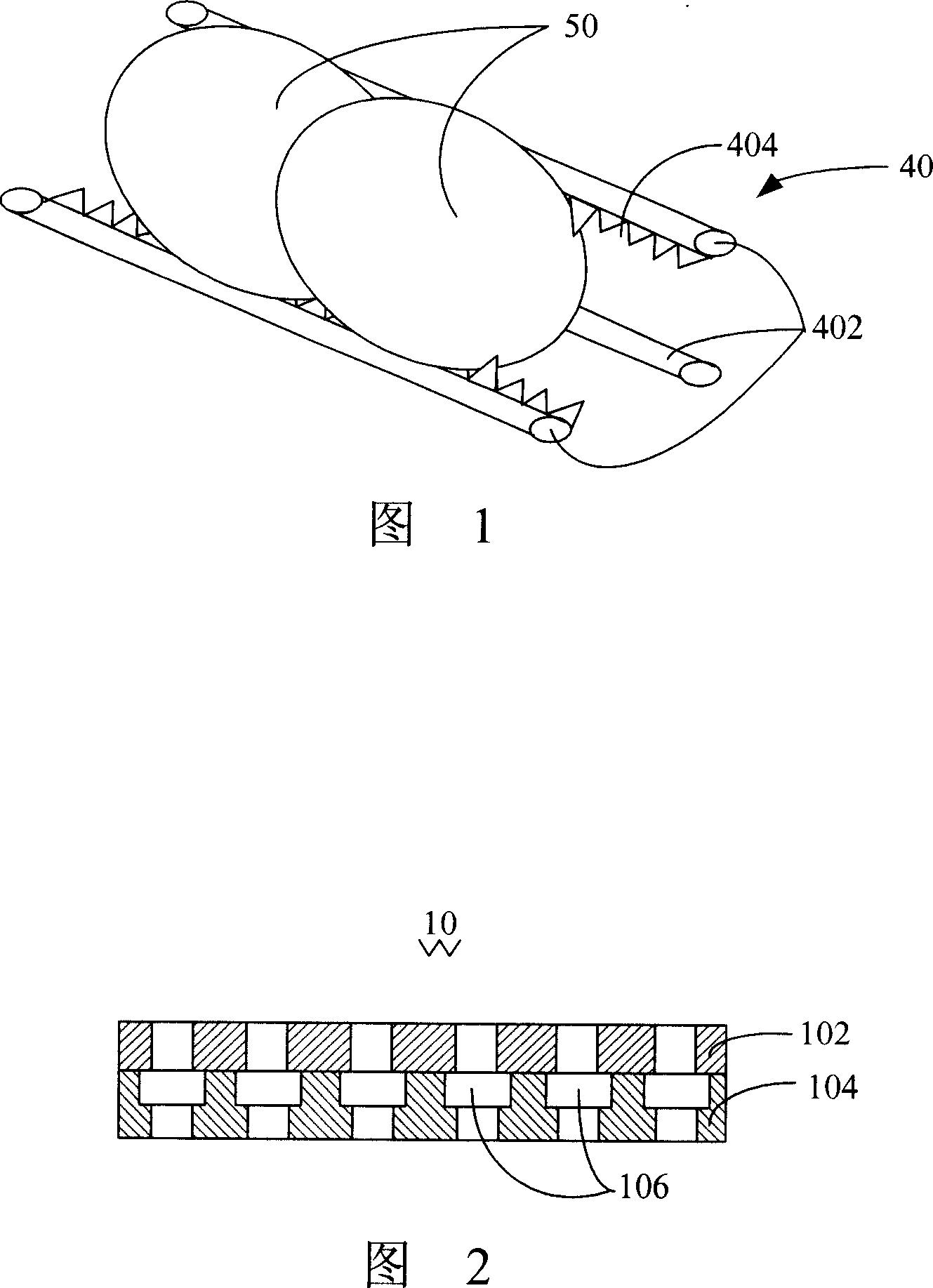
A technology for cleaning jigs and jigs, applied to cleaning methods and utensils, manufacturing tools, cleaning flexible objects, etc., can solve the problems that optical elements 50 are difficult to put in, take out, and damaged

Inactive Publication Date: 2008-01-23
HONG FU JIN PRECISION IND (SHENZHEN) CO LTD +1
View PDF0 Cites 4 Cited by
  • Summary
  • Abstract
  • Description
  • Claims
  • Application Information

AI Technical Summary

Problems solved by technology

However, the thickness and depth of the V-groove 404 formed by Teflon will block the water flow, so that the clamped part of the optical element 50 will not be cleaned cleanly. Furthermore, during the cleaning process, if the clamped optical element 50 is too loose, the optical Component 50 cannot withstand the later ultrasonic shock and falls off
Or the clamping is too tight, the optical element 50 is difficult to put in and take out, and it is easy to cause damage

Method used


Image

  • Cleaning fixture
  • Cleaning fixture
  • Cleaning fixture

Examples


Embodiment Construction

[0026] The embodiments of the present invention will be further described in detail below in conjunction with the accompanying drawings.

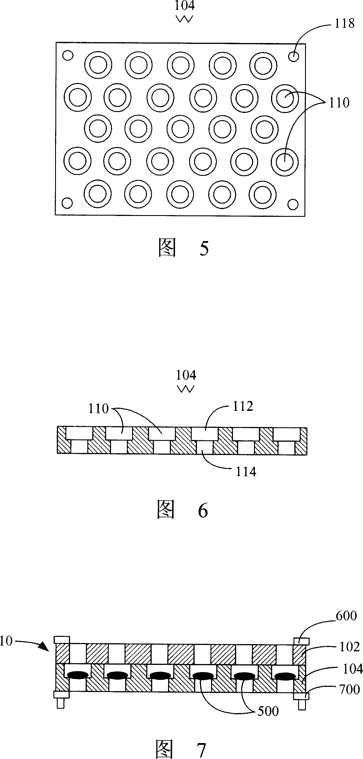
[0027] Please refer to FIG. 2 , the first embodiment of the present invention provides a cleaning jig 10 for cleaning optical components. The jig 10 includes a cover 102 and a body 104 . When the cover body 102 cooperates with the body 104 , a plurality of receiving spaces 106 for receiving optical components are formed in the jig 10 . The material of the jig 10 is one of aluminum, aluminum alloy, stainless steel, titanium alloy, copper and heat-resistant engineering plastics, and the jig 10 can be manufactured using CNC (Computerized Numerical Control) processing technology.

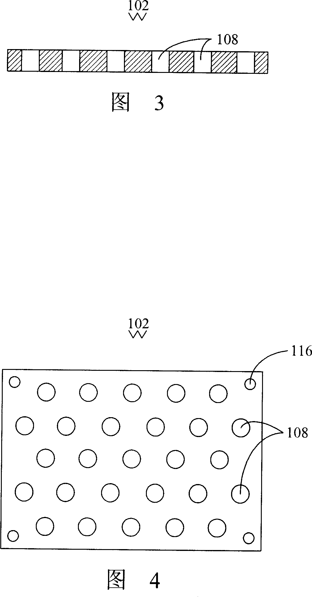
[0028] Please refer to FIG. 3 , the cover body 102 defines a plurality of first through holes 108 . The plurality of first through holes 108 are distributed on the cover 102 in a honeycomb arrangement at a certain distance, as shown in FIG. 4 , the first through hol...


PUM


Abstract

The invention relates to a washing fixture used for washing optical member, which comprises a lid and a main body. A plurality of first through holes are opened on the lid, which takes honeycomb shape array and are distributed on the lid. A plurality of second through holes which corresponds with the first through holes are opened on the main body, which takes honeycomb shape array and are distributed on the lid, each second through hole is provided with a first opening and a second opening, when the lid is coordinated with the main body, the first opening is more closer to the lid than the second opening, when the lid and the main body are washed together, a plurality of containing spaces which is used for collecting optical member are formed on the fixture. The containing space limits the optical member, to prevent the optical member fall off from the second openings of the first through hole and the second hole. The washing fixture, the honeycomb array way of the through holes can reach the large quantity of the through holes in the same fixture area, therefore increase the quantity of the collecting optical member for washing.

Description

technical field [0001] The invention relates to a clamping device, in particular to a cleaning jig for cleaning optical elements. Background technique [0002] With the development of multimedia technology, imaging equipment such as cameras, digital cameras, and mobile phone camera lenses are becoming more and more popular among consumers. The image quality puts forward higher requirements, that is, it is hoped that the image of the object to be photographed is clear, and the image quality of the object depends to a large extent on the quality of the optical instruments in the camera. [0003] The imaging module in the camera generally includes a lens, an optical filter and an image sensing element, such as a Charge Coupled Device (CCD for short), or a Complementary Metal-Oxide Semiconductor (CMOS for short). In the process of producing these optical components such as lenses and optical filters, in order to achieve a high degree of cleanliness, these optical components gen...

Claims


Application Information

Patent Timeline
Patent Type & Authority Applications(China)
IPC IPC(8): B08B11/02B08B3/04B25B11/00
Inventor 董才士
Owner HONG FU JIN PRECISION IND (SHENZHEN) CO LTD
Why Eureka
Try Eureka