Rough rolling vertical roller mill

A technology of vertical roll mill and rough rolling, which is applied in the direction of metal rolling stand, metal rolling mill stand, driving device for metal rolling mill, etc., and can solve the problems of reducing production efficiency, rolling roll accumulation funds, and increasing rough rolling area One-time equipment investment and other issues can be achieved to improve the transmission rigidity and service life, meet the requirements of large torque transmission, and shorten the time for online roll change

Inactive Publication Date: 2008-01-23
TIANJIN TIRNFR HEAVY HYDROELECTRIC FRCILITY CO LTD
View PDF0 Cites 29 Cited by
  • Summary
  • Abstract
  • Description
  • Claims
  • Application Information

AI Technical Summary

Problems solved by technology

The disadvantages of the above-mentioned rolling mill are: 1. It is necessary to prepare a lot of rolls suitable for various specifications and passes, even if some specifications are used in a small amount, they must be prepared, which will inevitably cause a waste of funds for rolling rolls.
2. The roll change in the existing rolling mill equipment is online roll change, and each roll change takes a lot of time, so the entire production line needs to be shut down, which greatly reduces the production efficiency
3. To realize flat roll reciprocating rolling, it must be equipped with auxiliary equipment such as a swing table, which increases the one-time equipment investment in the rough rolling area
4. The main drive reducer in the existing rolling mill adopts a split bevel gearbox structure, and the two bevel gearboxes are fixed by a pressure plate and connected by splines in the middle, so the overall rigidity of the transmission is poor and cannot meet the requirements of large torque transmission
5. The side pressing device of the rolling mill adopts a manual adjustment structure, and its disadvantages: a. Manual adjustment is manual adjustment of the roll surface, so the adjustment speed is slow
b. Manual adjustment can only adjust the roll gap in the shutdown state, and the roll gap will not change in the production state, so the strip pressure cannot be realized

Method used


Image

  • Rough rolling vertical roller mill
  • Rough rolling vertical roller mill
  • Rough rolling vertical roller mill

Examples


Embodiment Construction

[0021] In order to further understand the invention content, characteristics and effects of the present invention, the following examples are given, and detailed descriptions are as follows in conjunction with the accompanying drawings:

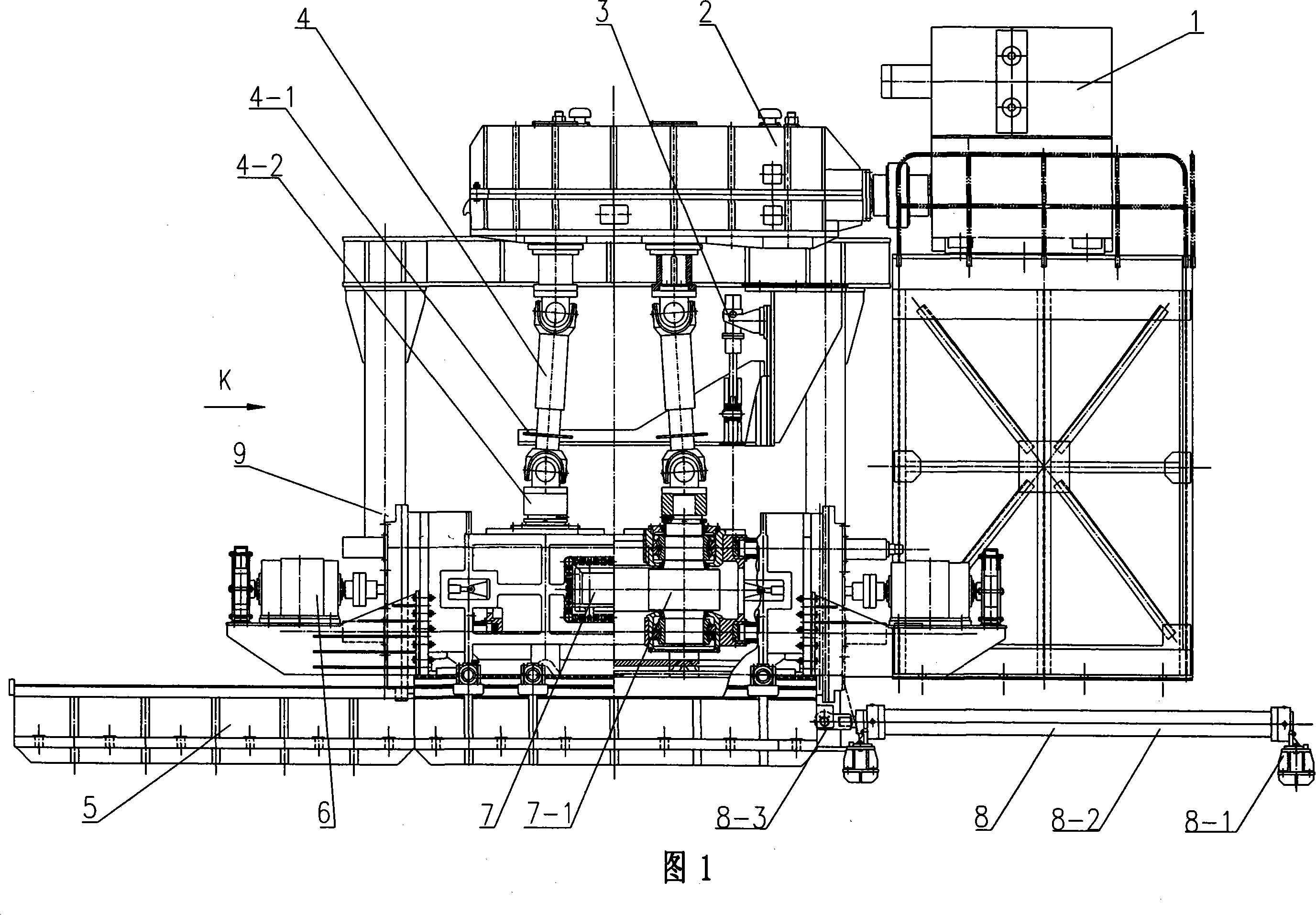
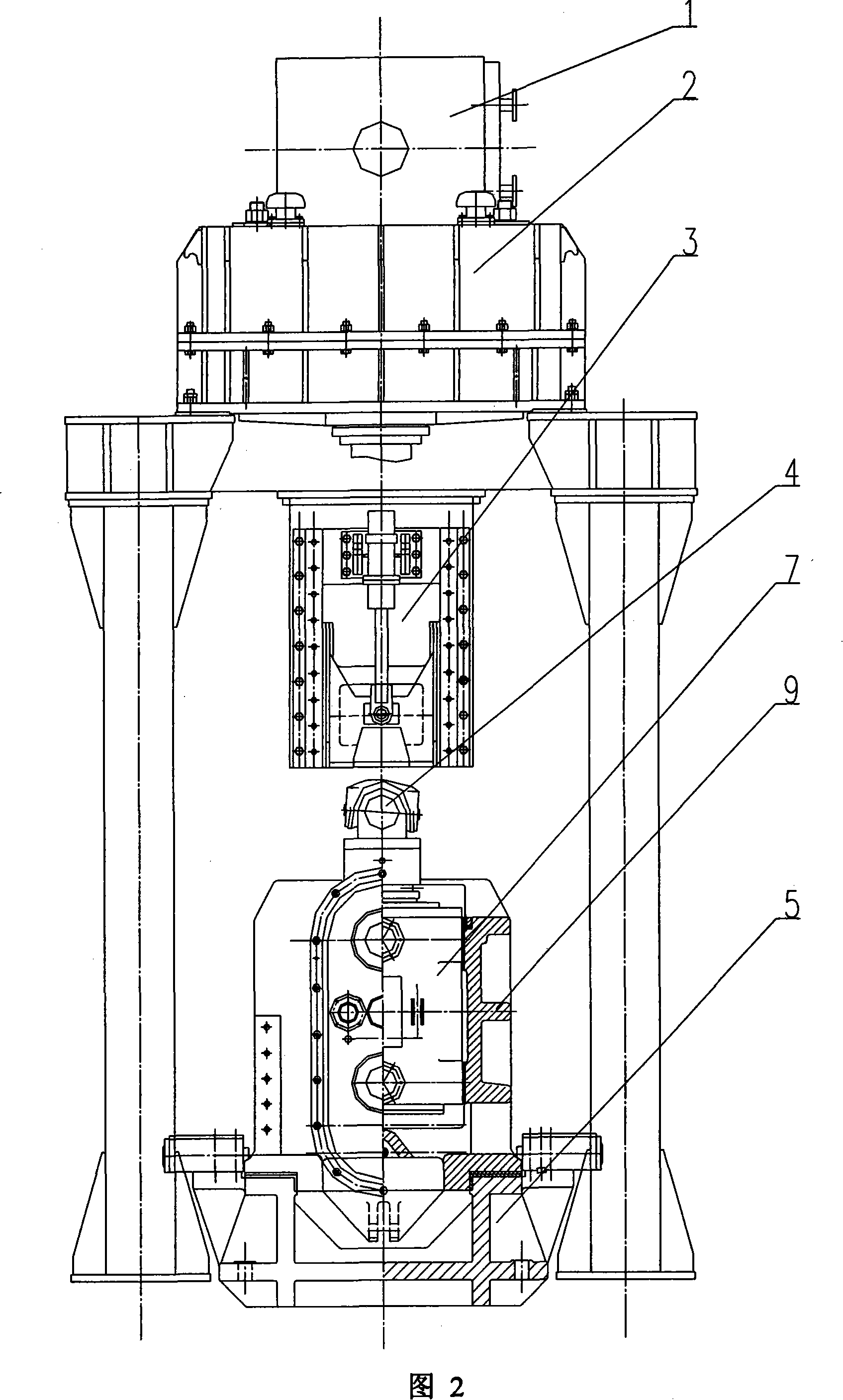
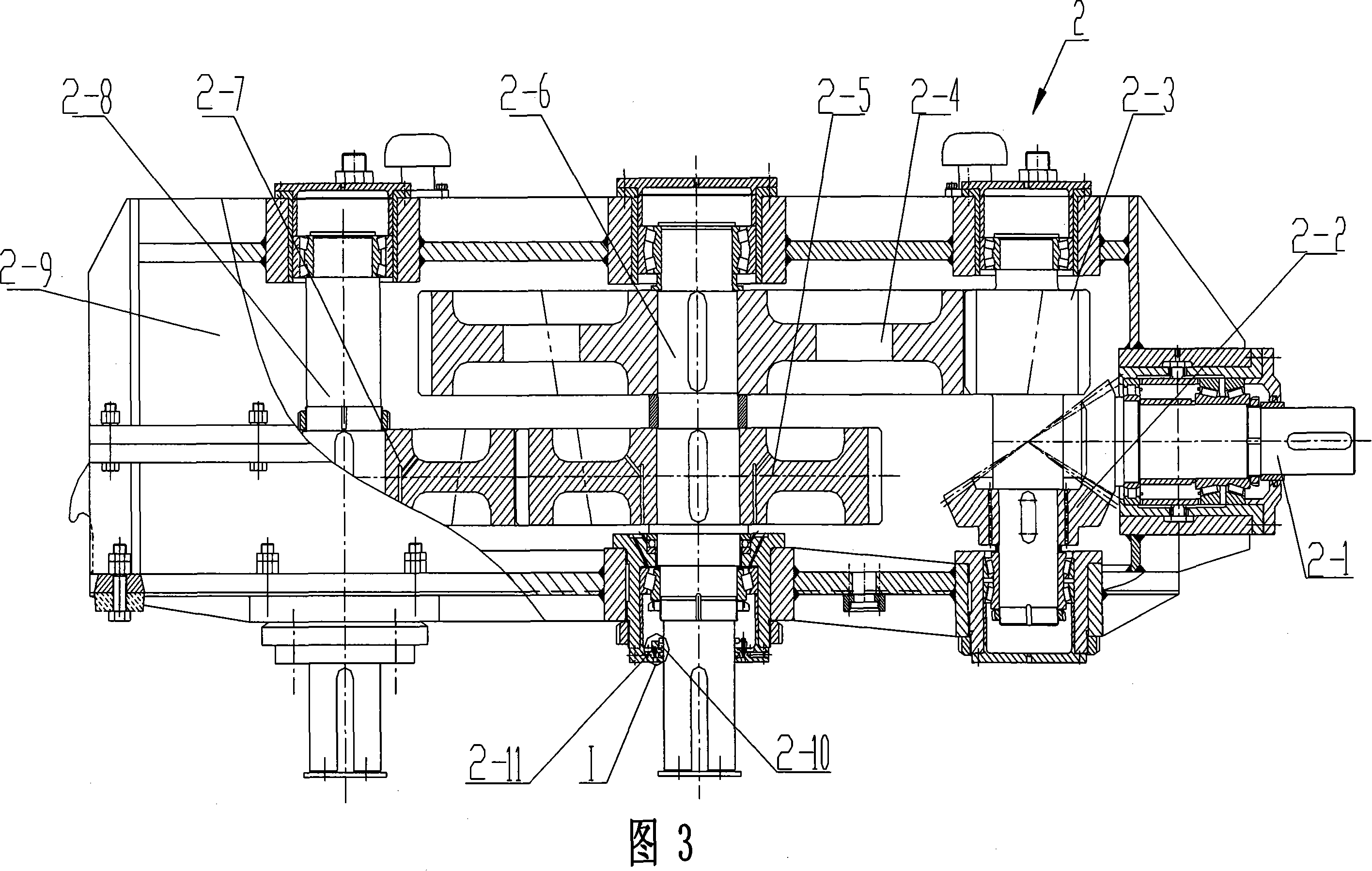
[0022] Please refer to Fig. 1-Fig. 2, rough rolling vertical roll mill, including: main drive motor 1, main drive combined reducer 2, cross universal joint shaft 4, frame 9, guide rail seat assembly 5, side pressing device 6, The rolling mill mechanism 7 and the roll changing mechanism 8, the main transmission combined speed reducer is an integral box structure, and its output shaft is two vertically installed output gear shafts 2-6 and 2-8, and the main transmission motor 1 The main drive combined reducer 2 is connected through a coupling, and the two output gear shafts protruding vertically below the main drive combined reducer are connected to the cross universal joint through the flange 4-1 and the sleeve 4-2 of the cross universal joint s...


PUM


Abstract

The invention relates to a rough rolling vertical milling caster is provided, wherein, the main transmission combination speed reducer is a whole structure, the output axle is two output gear axles arranged vertically, a main transmission motor is connected with the main transmission combine speed reducer by a shaft joint, the two output gear axles extending vertically under the main transmission combination speed reducer are connected with a cross universal spiale, a sleeve at the low end of the cross universal spiale is arranged on the roller platycephaly of a roller structure on a lead rail equipment, the two sides of the roller structure is connected with a side pressure screwdown equipment of a transmission bolt structure with direct current motor driving gear, a hydraulic pressure roll changing lifting device is arranged on a frame under the main transmission combination speed reducer, a side of the lead rail base equipment is arranged with a roll changing structure. The advantage of the invention is that: the invention improves the transmission rigidity and service life, which can meet the requirements of large torsion distance; the invention can realize quick roll changing, which shortens the online roll changing time greatly and improves work efficiency; the invention cooperates with a plain-barrel rolling machine, which can produce blank with different standard and lowers the process cost.

Description

technical field [0001] The invention belongs to the technical field of steel rolling machinery and equipment, and in particular relates to a rough rolling vertical roll mill suitable for blank rolling in the rough rolling area of ​​a medium and wide band hot rolling production line. Background technique [0002] At present, the rough rolling blanking machine commonly used in the medium and wide band hot rolling production line is usually a 70-800 flat roll mill, because only the flat roll mill is used, there is no vertical roll mill, and the finished products of different specifications must be rolled according to different billets. The corresponding pass type is prepared to adapt to the billet used and to prepare suitable profiles for the subsequent rolling process. Therefore, with the change of the finished product specifications of the medium and wide bands, it is necessary to constantly replace the rolls of different pass types. The shortcoming of above-mentioned rolling...

Claims


Application Information

Patent Timeline
Patent Type & Authority Applications(China)
IPC IPC(8): B21B35/00B21B35/12B21B31/08B21B31/22
Inventor 邢凤琦张世强王得仓单庆臣
Owner TIANJIN TIRNFR HEAVY HYDROELECTRIC FRCILITY CO LTD
Why Eureka
Try Eureka