Method for standardizing structural parameter of structure optical vision sensor

A technology of structural parameters and structured light, which is applied to instruments, optical devices, measuring devices, etc., can solve the problems of complicated operation, small number of calibration points, and high cost of processing tooth-shaped targets, and achieves expansion of the scope of application, simple operation, and improved performance. The effect of efficiency

Inactive Publication Date: 2008-01-23
BEIHANG UNIV
View PDF1 Cites 59 Cited by
  • Summary
  • Abstract
  • Description
  • Claims
  • Application Information

AI Technical Summary

Problems solved by technology

[0008] From the above analysis, it can be seen that the wire drawing method requires manual aiming multiple times, the operation is complicated, and an electronic theodolite is needed as an auxiliary device; the tooth-shaped target method has a limited number of calibration points due to the limited tooth edges, and the cost of processing the tooth-shaped target is high; The cross-ratio invariant method based on the planar target and the fast calibration method of the line structured light sensor based on the coplanar reference object have a small calibration range and are only suitable for calibrating line structured light or multi-line structured light

Method used


Image

  • Method for standardizing structural parameter of structure optical vision sensor
  • Method for standardizing structural parameter of structure optical vision sensor
  • Method for standardizing structural parameter of structure optical vision sensor

Examples


Embodiment Construction

[0029] The present invention will be further described in detail below in conjunction with the accompanying drawings and specific embodiments.

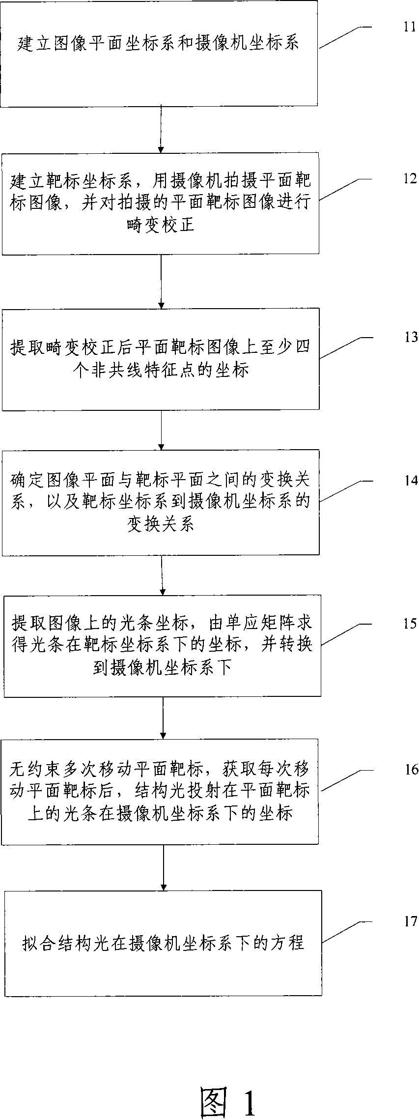
[0030] Fig. 1 is the overall implementation flowchart of the structural parameter calibration method of the structured light visual sensor of the present invention, as shown in Fig. 1, the calibration method of the present invention includes the following steps:

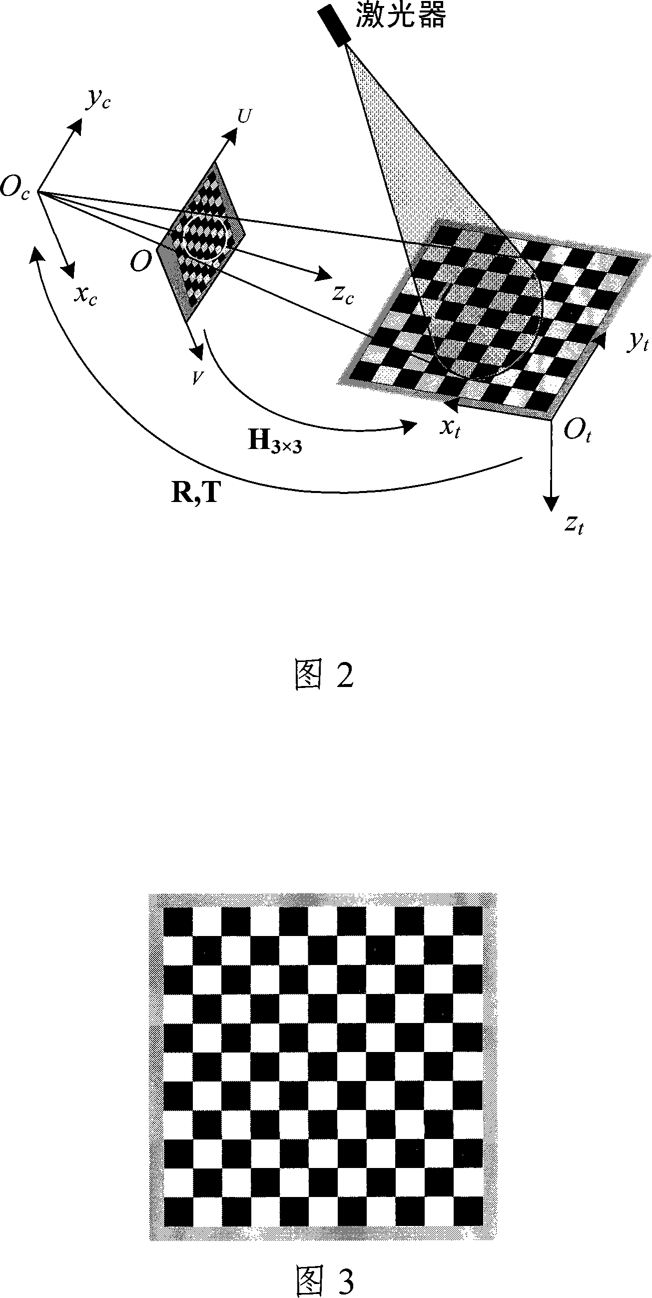
[0031] Step 11: Establish image plane coordinate system and camera coordinate system. As shown in Figure 2, the camera coordinate system O is established according to the placement position of the camera c -x c the y c z c and the camera image plane coordinate system O-UV.

[0032] Step 12: Establish a target coordinate system, use a camera to capture a planar target image, and perform distortion correction on the captured planar target image. Turn on the power of the laser projector, place a planar target with feature points in the measurement area of ​​the structured ...


PUM


Abstract

The invention discloses a calibrating method for the structural parameters of a vision sensor for a structure light, which comprises: setting up a coordinate system for a camera, for the plane of the images, and for a target; determining coordinates of the light stripes in the camera coordinate system that are projected by the structure light on the plane target; moving in no-restricting way several times the plane target and getting the coordinates of the light stripes in the camera coordinate system that are projected by the structure light on the plane target after each movement of the plane target; adapting a function for the structure light depending upon all coordinates of the light stripes obtained. The method is easy to operate, needs no auxiliary devices, can not only improve the calibrating efficiency of structure light, but also increase the application range for the calibration of structure light.

Description

technical field [0001] The invention relates to a structured light vision measurement technology, in particular to a structural parameter calibration method of a structured light vision sensor. Background technique [0002] Structured light visual inspection is a detection method that uses a camera to capture the measuring point or measuring light strip image formed by the intersection of the structured light emitted by the laser and the surface of the measured object, and then uses the principle of laser triangulation to obtain the three-dimensional information of the object surface. According to the laser projection mode, structured light visual detection can be divided into point structured light, single line structured light, multi line structured light, circular structured light and other modes. Structured light visual inspection has the advantages of large range, non-contact, fast speed, good system flexibility, and moderate accuracy. It is widely used in reverse engin...

Claims


Application Information

Patent Timeline
Patent Type & Authority Applications(China)
IPC IPC(8): G01B11/00G01B11/24G01B11/25
CPCG01B11/2504A61B1/0605
Inventor 孙军华张广军魏振忠
Owner BEIHANG UNIV
Why Eureka
Try Eureka